
Mechanical Relay Guide
Mechanical relays can switch a power or signal line by physically moving metal contacts with an electromagnet. Learn more here.

Quantity Available: 360
| Qty | Price |
|---|---|
| 10 | $90.25 |
| 25 | $80.75 |
| 50 | $71.25 |
| 100 | $66.50 |
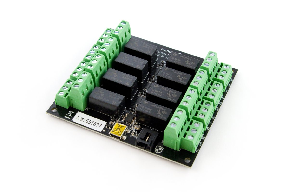
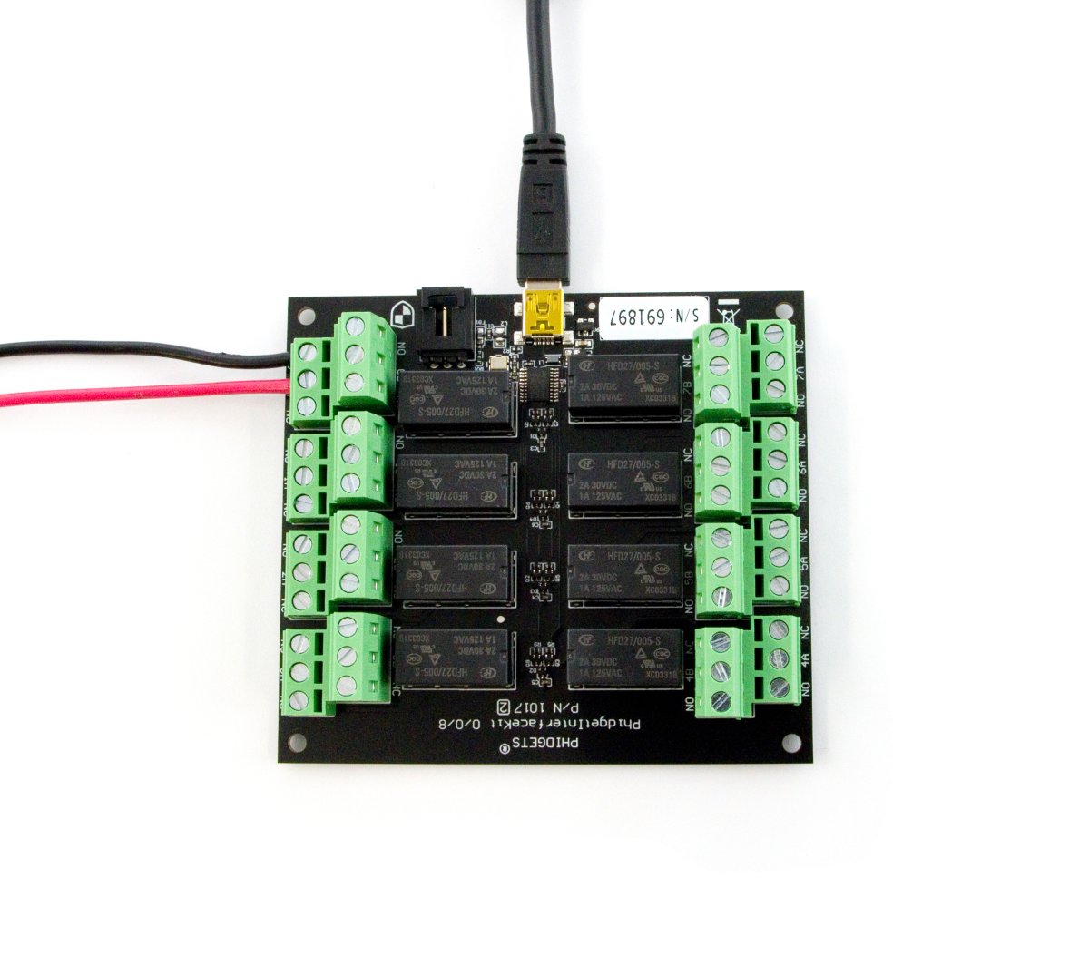
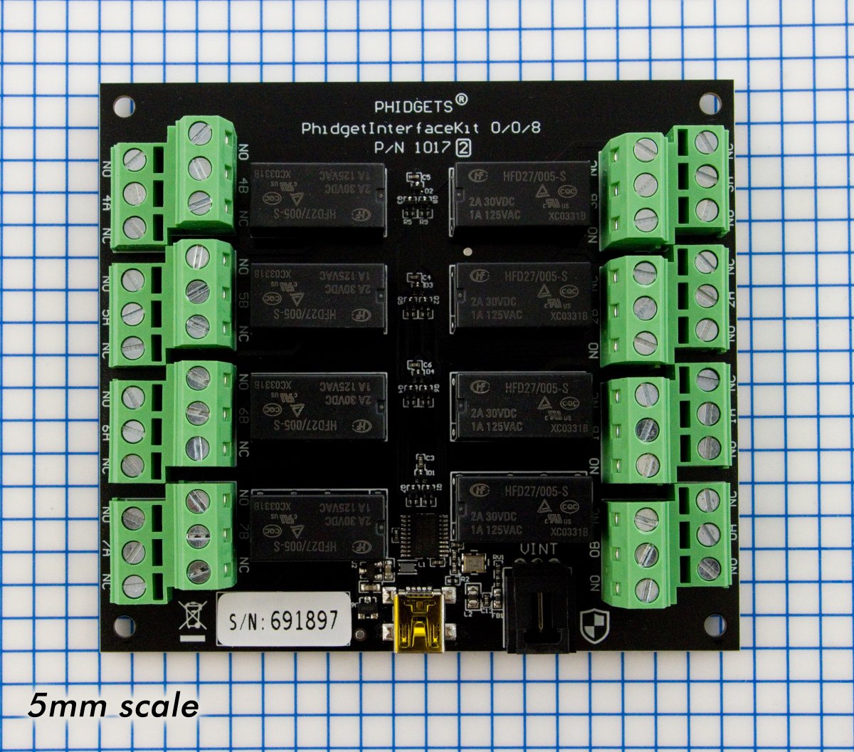
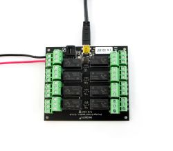
The PhidgetInterfaceKit 0/0/8 is a mechanical relay board designed to switch signals.
It includes eight DPDT mechanical relays capable of switching AC or DC signals. While typical mechanical relay boards are unable to switch signals due to an oxide buildup on the contacts, this product excels at switching both signals and low-power applications.
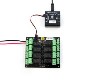
You can connect the PhidgetInterfaceKit 0/0/8 directly to your computer via USB or through a VINT Hub Phidget.
Note: These relays cannot be switched at maximum current and maximum voltage at the same time. Ensure that the total power of the load does not exceed the switching power of the relay.

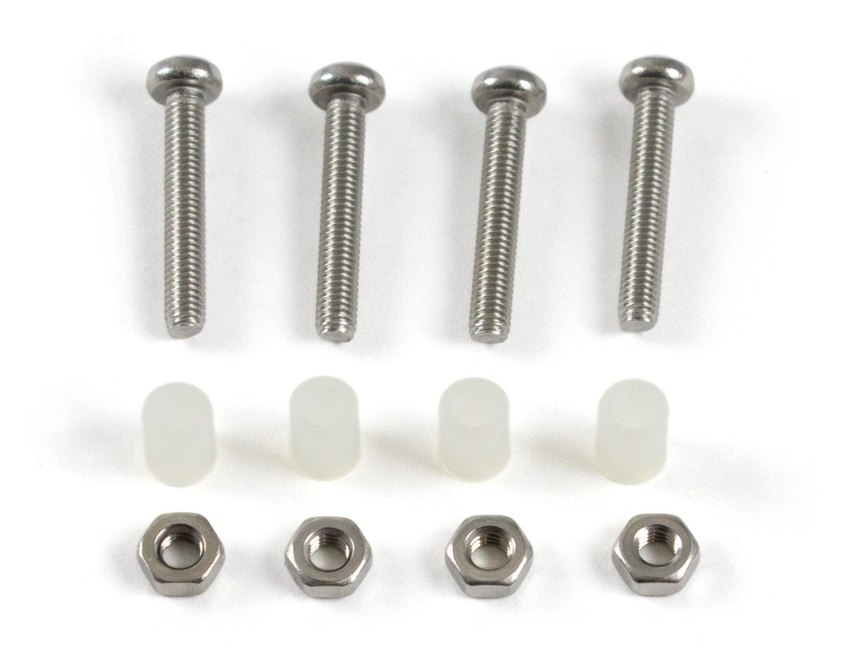
Welcome to the 1017 user guide! In order to get started, make sure you have the following hardware on hand:
Next, you will need to connect the pieces:
Now that you have everything together, let's start using the 1017!
In order to demonstrate the functionality of the 1017, the Phidget Control Panel running on a Windows machine will be used.
The Phidget Control Panel is available for use on both macOS and Windows machines.
To open the Phidget Control Panel on Windows, find the ![]() icon in the taskbar. If it is not there, open up the start menu and search for Phidget Control Panel
icon in the taskbar. If it is not there, open up the start menu and search for Phidget Control Panel
To open the Phidget Control Panel on macOS, open Finder and navigate to the Phidget Control Panel in the Applications list. Double click on the ![]() icon to bring up the Phidget Control Panel.
icon to bring up the Phidget Control Panel.
For more information, take a look at the getting started guide for your operating system:
Linux users can follow the getting started with Linux guide and continue reading here for more information about the 1017.
After plugging the 1017 into your computer and opening the Phidget Control Panel, you will see something like this:
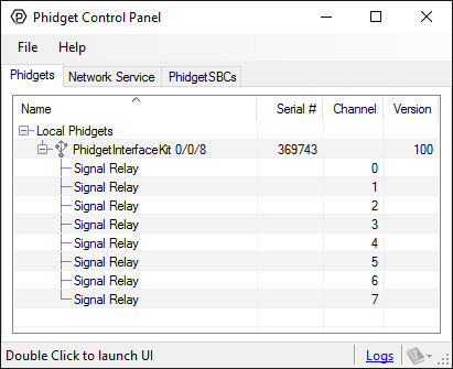
The Phidget Control Panel will list all connected Phidgets and associated objects, as well as the following information:
The Phidget Control Panel can also be used to test your device. Double-clicking on an object will open an example.
Double-click on a Digital Output object labelled Signal Relay in order to run the example:
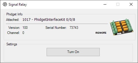
General information about the selected object will be displayed at the top of the window. You can also experiment with the following functionality:
Before you can access the device in your own code, and from our examples, you'll need to take note of the addressing parameters for your Phidget. These will indicate how the Phidget is physically connected to your application. For simplicity, these parameters can be found by clicking the button at the top of the Control Panel example for that Phidget.

In the Addressing Information window, the section above the line displays information you will need to connect to your Phidget from any application. In particular, note the Channel Class field as this will be the API you will need to use with your Phidget, and the type of example you should use to get started with it. The section below the line provides information about the network the Phidget is connected on if it is attached remotely. Keep track of these parameters moving forward, as you will need them once you start running our examples or your own code.

You are now ready to start writing your own code for the device. The best way to do that is to start from our Code Samples.
Select your programming language of choice from the drop-down list to get an example for your device. You can use the options provided to further customize the example to best suit your needs.
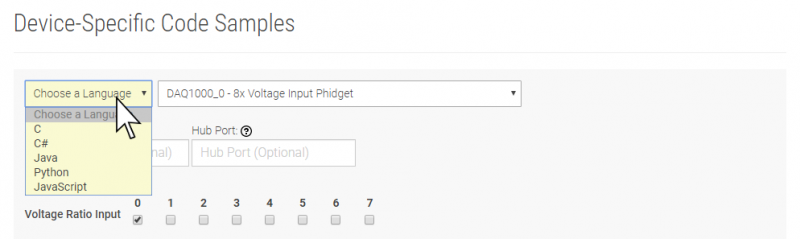
Once you have your example, you will need to follow the instructions on the page for your programming language to get it running. To find these instructions, select your programming language from the Programming Languages page.
A relay is an electrically-controlled switch. Although many types of electrical switches exist, a relay’s mechanical nature gives it the advantage of reliability and current-switching capacity. The main disadvantage to using mechanical relays is their limited life-span, as opposed to solid state relays who do not suffer from this drawback. For more information, check the Mechanical Relay Guide and the Solid State Relay Guide.
Relays have a connection scheme determined by the arrangement of contacts within the relay. Because relays are a type of switch, they are defined in the same way other electromechanical switches are defined.
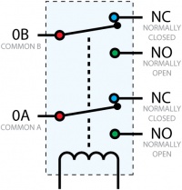
In switch schemes, the number of poles represents the number of common terminals a switch has, and the number of throws represents the number of switchable terminals that exist for each pole. The relays used in the InterfaceKit 0/0/8 are DPDT relays: double pole, double throw. The internal construction of this type of relay is depicted in the diagram above. Many other types of relays exist: SPST, DPDT, and DPST, to name a few.
In a relay, one of the throw terminals is labelled normally closed (NC), and the other is labelled normally open (NO). As the name indicates, the normally closed terminal is the terminal connected to common when the relay coil is not powered. When the relay coil is energized by the relay control circuit, the electromagnetic field of the coil forces the switch element inside the relay to break its contact with the normally closed terminal and make contact with the normally open terminal. The switch element would then connect the normally open terminal and the common terminal.
These relays cannot be switched at maximum current and maximum voltage at the same time. Ensure that the total power of the load does not exceed the switching power of the relay. For example, you can switch these relays at 200V DC and 0.3 A (60W), or 30VDC and 2A (60W), but not 200VDC and 2A (400W).
When a relay is in one switch position for a period of time, oxidation of the open contact(s) can occur. Depending upon the internal coating material of the contacts, oxide films of varying density will be displaced upon the surface of open contacts; this film acts as an insulator to current flow. When the relay is switched, a certain amount of current flowing through the contacts, known as the wetting current, is required to remove the film of oxides and ensure proper conduction. The wetting current required to operate this relay is low enough for use in signal switching applications. Check the specification table for your relay board to find out the Minimum Load Current or Wetting Current.
If highly inductive loads are used with this InterfaceKit, it is recommended that a noise limiting component be used to prevent damage to the device. An MOV, TVS diode, or kickback diode (for DC applications) shunted across the load will assist in dissipating voltage transients.
| Board Properties | |
|---|---|
| Controlled By | VINT / USB (Mini-USB) |
| USB Stack | PHIDUSB |
| Driver Support | Phidget22 |
| API Object Name | DigitalOutput |
| Current Consumption Min | 14 mA |
| Current Consumption Max | 340 mA |
| USB Speed | Low Speed |
| VINT Communication Speed Max | 100 kbit/s |
| Physical Properties | |
| Switch Type | DPDT |
| Recommended Wire Size | 12 - 24 AWG |
| Switching Speed Max | 20 cpm |
| Operating Temperature Min | 0 °C |
| Operating Temperature Max | 70 °C |
| Electrical Properties | |
| Dielectric Strength | 1.5 kV AC |
| Contact Resistance Max | 50 mΩ |
| Load Voltage Max (DC) | 120 V DC |
| Load Voltage Max (AC) | 250 V AC |
| Load Current Min | 10 μA |
| Load Current Max (DC) | 2 A |
| Load Current Max (AC) | 2 A |
| Turn-on Time Max | 15 ms |
| Turn-off Time Max | 15 ms |
| Switching Power Max (Real) | 60 W |
| Switching Power Max (Apparent) | 125 VA |
| Current Consumption Min | 14 mA |
| Current Consumption Max | 300 mA |
| Customs Information | |
| Canadian HS Export Code | 8471.80.00 |
| American HTS Import Code | 8471.80.40.00 |
| Country of Origin | CN (China) |
| Date | Board Revision | Device Version | Packaging Revision | Comment |
|---|---|---|---|---|
| February 2008 | 0 | 100 | Product Release | |
| February 2011 | 1 | 100 | Different board size. Replaced USB connector with Mini-USB connector. Larger terminal blocks. | |
| January 2018 | 1 | 100 | B | Removed USB cable from packaging |
| September 2022 | 2 | 200 | Added VINT connector | |
| August 2022 | 2 | 210 | Added support for DutyCycle on USB mode | |
| May 2023 | 2 | 211 | USB bug fixes | |
| April 2024 | 2 | 212 | Improved latency, faster polling interval |
| Channel Name | API | Channel | Interface |
|---|---|---|---|
| PhidgetInterfaceKit 0/0/8 | |||
| Signal Relay | DigitalOutput | 0 - 7 | USB |
| PhidgetInterfaceKit 0/0/8 | |||
| Signal Relay | DigitalOutput | 0 - 7 | VINT |
You can protect your board from dust and debris by purchasing an enclosure. An enclosure will also prevent unintentional shorts caused by objects touching the pins on the bottom of the board or any terminal screws.
| Product | |
|---|---|
| Part Number | Price |
 Acrylic Enclosure for the 1017
|
$11.00 |
This Phidget can be controlled by a VINT Hub or directly from your computer's USB port. For more information about VINT, have a look at the VINT Overview page. You can use a Phidget Cable to simply and easily connect this device to a VINT Hub. Here's a list of all of the different hubs currently available:
| Product | Board Properties | |||
|---|---|---|---|---|
| Part Number | Price | Number of VINT Ports | VINT Communication Speed Max | Controlled By |
 VINT Hub Phidget
|
$40.00 | 6 | 1 Mbit/s | USB (Mini-USB) |
 1-Port VINT Hub Phidget
|
$26.00 | 1 | 1 Mbit/s | USB (USB-A) |
 Wireless VINT Hub
|
$65.00 | 6 | 100 kbit/s | Local Network (Ethernet or Wi-Fi) |
 PhidgetSBC4
|
$130.00 | 6 | 100 kbit/s | — |
Use a USB cable if you want to connect this Phidget directly to your computer. We have a number of different lengths available, although the maximum length of a USB cable is 5 meters due to limitations in the timing protocol. For longer distances, we recommend that you use a Single Board Computer to control the Phidget remotely.
| Product | Physical Properties | |||
|---|---|---|---|---|
| Part Number | Price | Connector A | Connector B | Cable Length |
 USB-A to Mini-B Cable 28cm 24AWG
|
$3.00 | USB Type A | USB Mini-B | 280 mm |
 USB-A to Mini-B Cable 28cm Right Angle
|
$3.50 | USB Type A | USB Mini-B (90 degree) | 280 mm |
 USB-A to Mini-B Cable 60cm 24AWG
|
$3.50 | USB Type A | USB Mini-B | 600 mm |
 USB-A to Mini-B Cable 83cm Right Angle
|
$4.50 | USB Type A | USB Mini-B (90 degree) | 830 mm |
 USB-A to Mini-B Cable 120cm 24AWG
|
$4.00 | USB Type A | USB Mini-B | 1.2 m |
 USB-A to Mini-B Cable 180cm 24AWG
|
$4.00 | USB Type A | USB Mini-B | 1.8 m |
 USB-A to Mini-B Cable 450cm, 20 AWG 2C
|
$12.00 | USB Type A | USB Mini-B | 4.5 m |
 USB-C to Mini-B Cable 60cm 24AWG
|
$5.00 | USB Type C | USB Mini-B | 600 mm |
 USB-C to Mini-B Cable 180cm 24AWG
|
$6.00 | USB Type C | USB Mini-B | 1.8 m |
Use a Phidget cable if you want to connect this device to a VINT Hub. You can solder multiple cables together in order to make even longer Phidget cables, but you should be aware of the effects of having long wires in your system.
| Product | Physical Properties | |
|---|---|---|
| Part Number | Price | Cable Length |
 Phidget Cable 10cm
|
$1.50 | 100 mm |
 Phidget Cable 30cm
|
$1.75 | 300 mm |
 Phidget Cable 60cm
|
$2.00 | 600 mm |
 Phidget Cable 60cm
|
$2.00 | 600 mm |
 Phidget Cable 90cm
|
$2.00 | 900 mm |
 Phidget Cable 120cm
|
$2.25 | 1.2 m |
 Phidget Cable 150cm
|
$2.50 | 1.5 m |
 Phidget Cable 180cm
|
$2.75 | 1.8 m |
 Phidget Cable 350cm
|
$3.00 | 3.5 m |
 Phidget Cable Kit
|
$10.00 | 80 mm |
 Phidget Cable Extension Wire 22AWG
|
$0.75/Meter | — |
| Product | Electrical Properties | ||||
|---|---|---|---|---|---|
| Part Number | Price | Load Current Max (AC) | Load Voltage Max (AC) | Load Current Max (DC) | Load Voltage Max (DC) |
 PhidgetInterfaceKit 0/0/4
|
$60.00 | 12 A | 277 V AC | 7 A | * 30 V DC |
 4x Relay Phidget
|
$34.00 | 12 A | 277 V AC | 7 A | * 30 V DC |
 Relay Phidget
|
$12.00 | 12 A | 277 V AC | 7 A | * 30 V DC |
 Dual Relay Board
|
$17.00 | 12 A | 277 V AC | 7 A | * 30 V DC |
 PhidgetInterfaceKit 0/0/8
|
$95.00 | 2 A | 250 V AC | 2 A | 120 V DC |
 Signal Relay Phidget
|
$12.00 | 2 A | 240 V AC | 2 A | 120 V DC |
 PhidgetInterfaceKit 0/16/16
|
$105.00 | — | — | — | — |
 4x Isolated Solid State Relay Phidget
|
$28.00 | — | — | (per channel) 8 A | (per channel) 30 V DC |
 16x Isolated Solid State Relay Phidget
|
$56.00 | — | — | (per channel) 8 A | (per channel) 30 V DC |
 Solid State Relay Phidget
|
$15.00 | 10 A | 30 V AC | * 10 A | 30 V DC |
 Dual SSR Relay Board
|
$34.00 | (per channel) 9 A | 28 V AC | (per channel) 9 A | 40 V DC |
 SSR Relay Board 2.5A
|
$17.00 | 2.5 A | 28 V AC | 2.5 A | 40 V DC |
 Power Plug Phidget
|
$20.00 | 15 A | 125 V AC | — | — |
 PhidgetInterfaceKit 0/0/4
|
$60.00 | 12 A | 277 V AC | 7 A | * 30 V DC |
 PhidgetInterfaceKit 0/0/8
|
$95.00 | 2 A | 250 V AC | 2 A | * 120 V DC |
 SSR Relay Board 0.5A
|
$5.00 | 500 mA | 28 V AC | 500 mA | 40 V DC |