Interactive Garden Project
A series of ten articles on a sensory interactive garden project using Phidgets showcased at Beakerhead 2014.
by Kat

Part 1: The Growth of a Garden Begins
It begins as a grand idea. A flowering archway welcomes you onto a curving pathway. Fields of grass alight around your ankles, towering trees sing above your head and benches respond to your pressure, colouring a digital sky complete with a custom soundtrack. The landscape would take up a mere 1000 square feet.
Scaling back seems necessary. I cut down the trees, unpave the meandering pathway, and gather the swaths of grass. Then, into a more manageable flower-bed they go.
The main goal behind this project is interaction. One of its destinations will be Calgary's Beakerhead, it must showcase “science, technology, engineering and math in an outstanding, creative way.” Luckily, a project with as many lights, motors and programming as what I have in mind will make it easy to incorporate all of those elements.
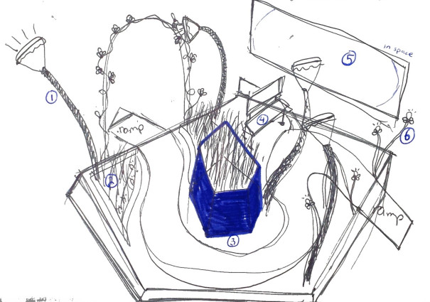
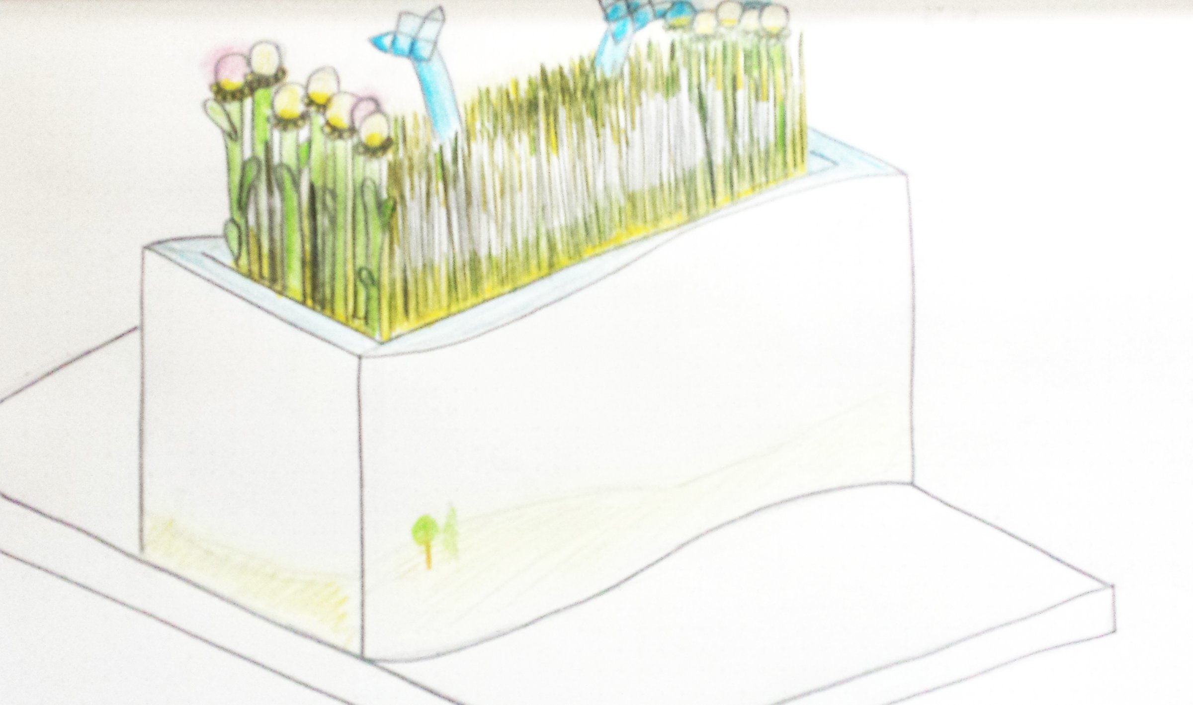
Before getting carried away with the fine details of the design, I have to think what is going to draw people toward the garden? Lights usually do a pretty good job at achieving this, some motion, too. The “grass” will be lit from the bottom and flower bulbs will twinkle at the ends. As a born and raised Albertan, I find something inherently beautiful in fields of gently waving wheat. Inspired by the duck machine, I thought of connecting grassy boards to motors that will make them rise and fall. The idea came around to look something like this:
I collected more ideas for the garden on a Pinterest board. Everything from Battlestar Galactica to origami collected on the wall.
Ideas continue to flow, watering the project so it becomes more solidified and fruitful. At this point, the garden feels firmly rooted and a solid picture of what it will be has emerged: People will come onto the platform surrounding the flower bed. The digital plants wake up and dim, ready to respond to interaction. Moving one's hands through the grass causes the lights around to glow brighter and the sounds to change pitch. The tall flowers bookending the field play like a musical instrument when touched. It's a little piece of garden serenity, grown from technology and science!
Part 2: The Technical Details
As the ideas for the garden coalesce and become cemented, it becomes time for actual planning. That means drawings, measurements and maths. I'm lucky, I love maths (and drawing).
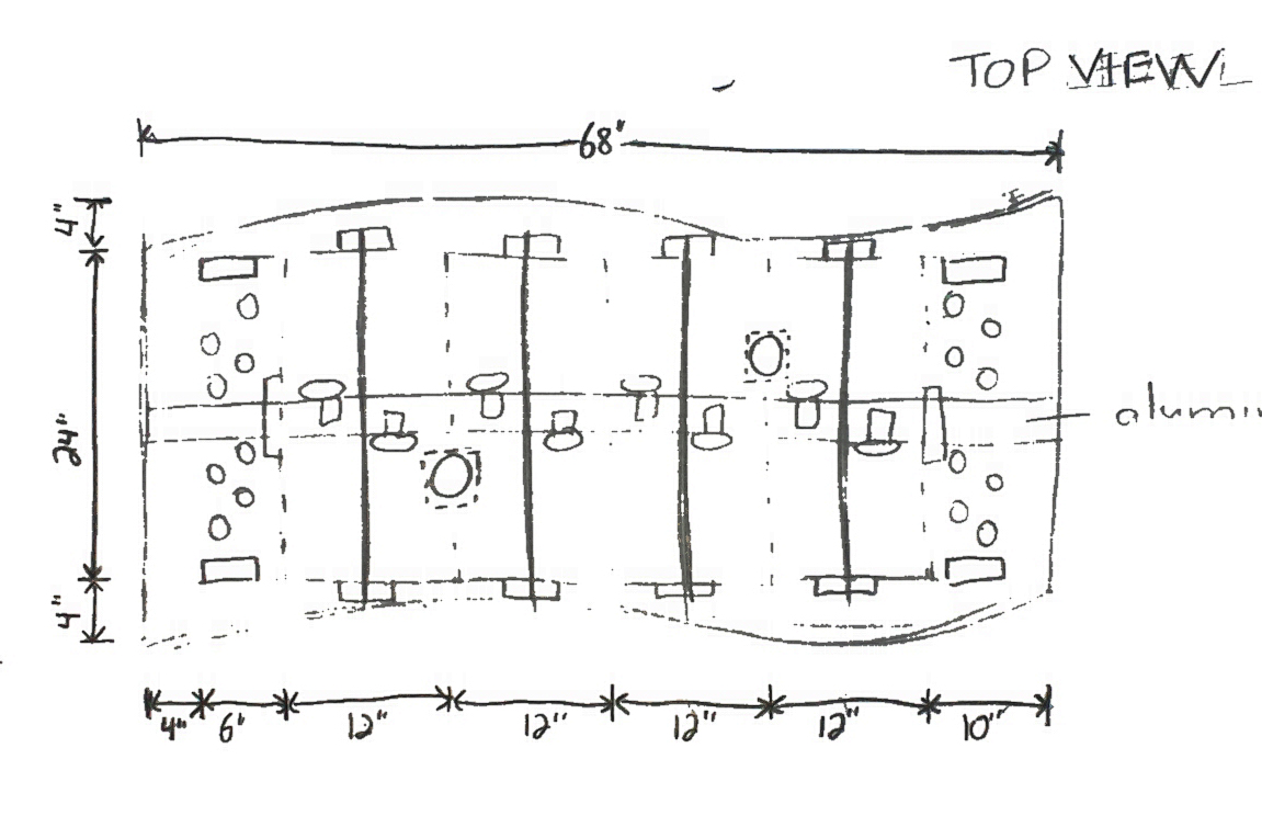
I've gone through fourteen pages of sketches, starting off with sixteen planks for the grass with an additional two on either end for the larger flowers, and eventually settling on eight 12″x12″ plywood planks (keeping the two stationary 6″x24″ ones on the end). The paring down is in consideration of size and complexity.
A 30″ height of the base is the same height as an average desk, which seems a good starting point. The grass and flowers will extend another 18″ above that, making it easy to interact with.
There'll be three plywood sheets for stability and fifteen stacks of 4x4s to hold it up. I won't go into the nitty gritty details, but you can get the idea from the pictures. The plywood sheets will be given curved sides so that paperboard can be nailed to them and hold the curve.
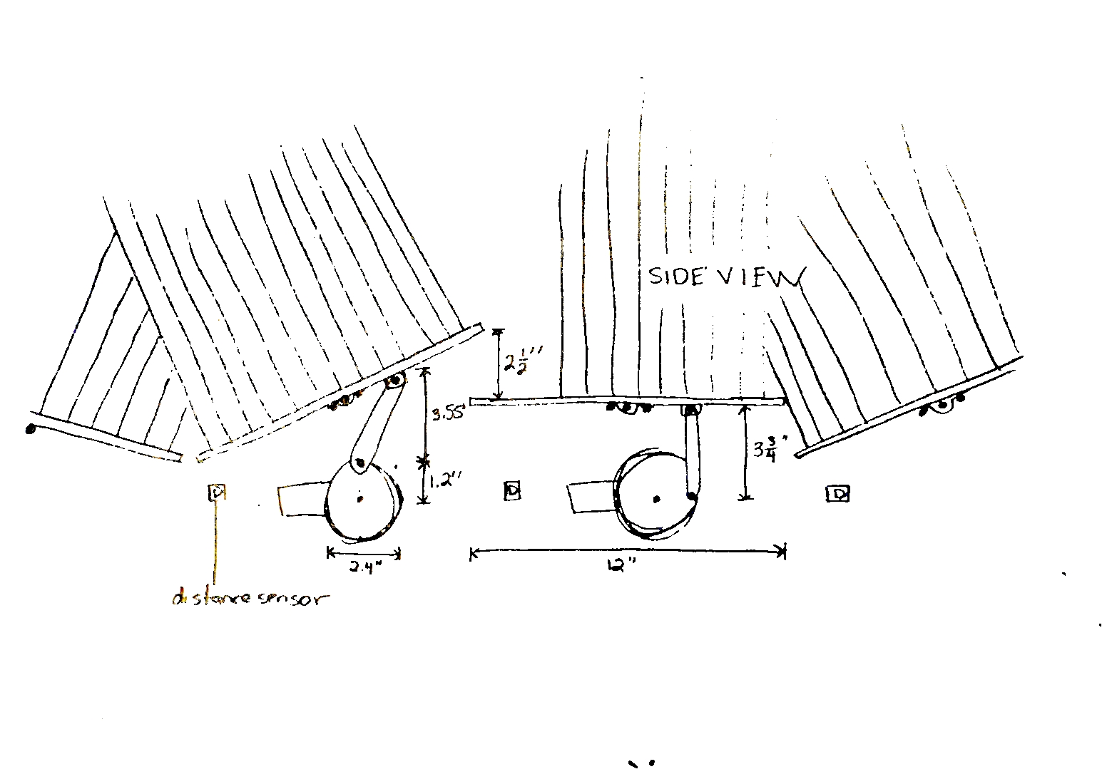
I'll use DC motors (servo motors, although precise, are also really noisy). Because of the structure's supports, there won't be an excess of room to work with between the upper plywood and the planks. I do some trigonometry, knowing that I want the edges of the boards to rise about 2.5″. I have to play with a couple variables to find out an ideal configuration that gives a reasonable length of arm and a reasonable size of motor horn.
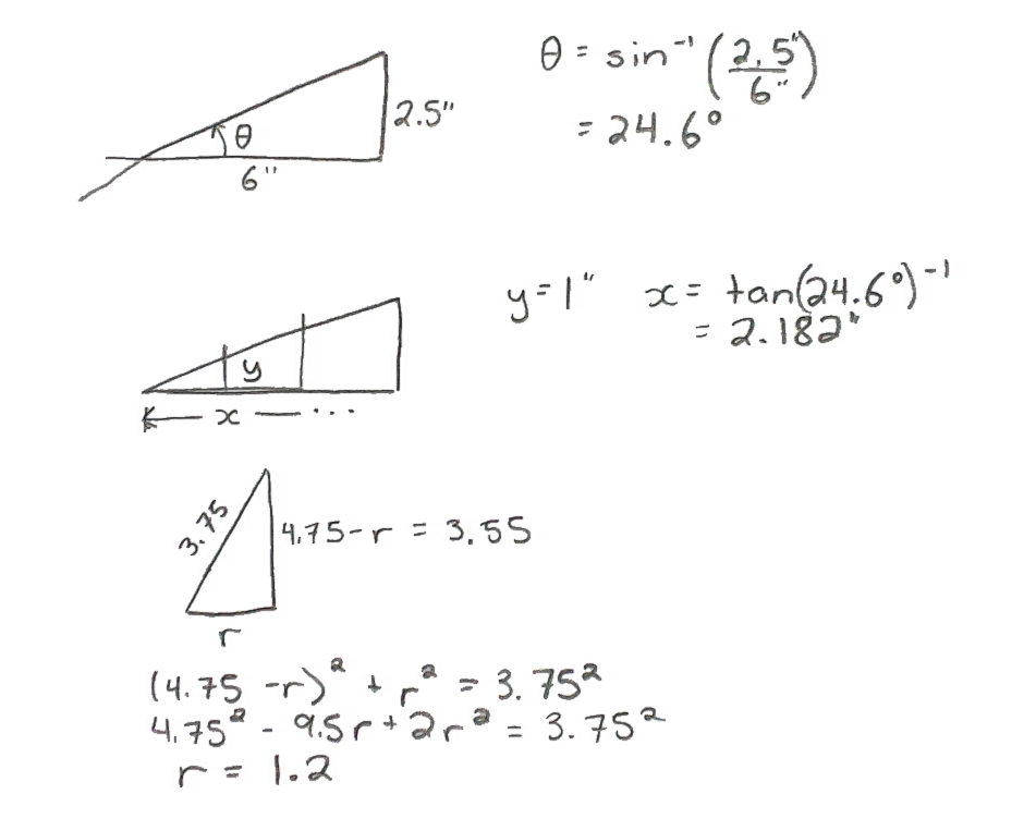
I find that an arm of length 3.75″ and a horn with a radius of 1.2″ centred 0.98″ from the middle of the plank will give the desired lift and still fit under the structure.
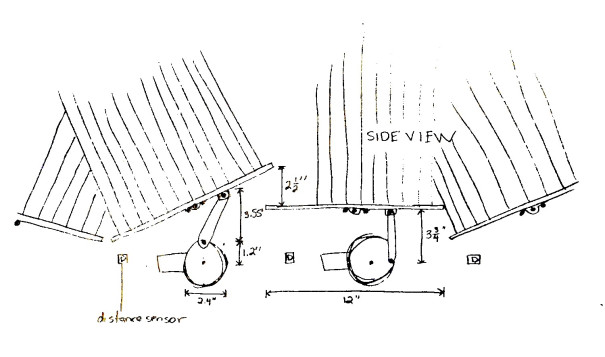
The final component to figure out is the base that people will approach on. There'll be a couple of load cells to sense the force of people standing on top of the base. It has to be big enough for a few people so it will extend 2.5′ on either side of the structure, making the entire thing a grand 7'x 5.67′. I'll use some thick plywood for the top of the base and 2x6s for the edge. In the middle I'll use 2x4s so that there's some clearance between the load cell and the wood, until people step on it. Since wood is quite soft, there'll need to be steel plates on the wood where it touches the load cell. Sounds solid.
Now it's on to testing some of these ideas…
Part 3: Getting my Hands Dirty
With six weeks until Beakerhead, I realize the scope of the garden is far more tremendous than I can manage. I've decided to pull back on a couple design elements: the motors and the load platform. These were both cumbersome and complex parts that I see being the most prone to error. The load platform will also be easy to add later, if time permits.
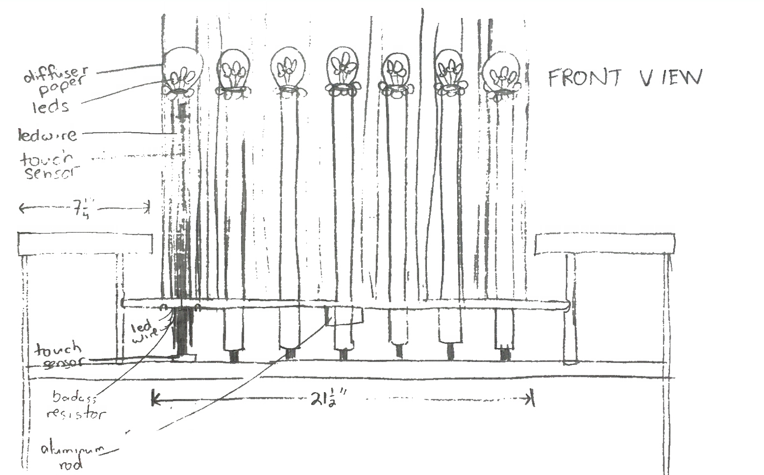
Deciding this, I started some prototype tests. I fixed a touch sensor onto a metal pole, which will be used for activating one-off sounds. It works! As my hand came close to the pole, the sensor picks up on my presence. The pole picked up my presence at about 3cm away, which is a bit too sensitive for my liking. I'll need to experiment with some different capacitances on C1 (the 1129 Touch Sensor comes with a 10nF capacitor), most likely lowering the value. However, the sensitivity may change once it's installed around different objects.
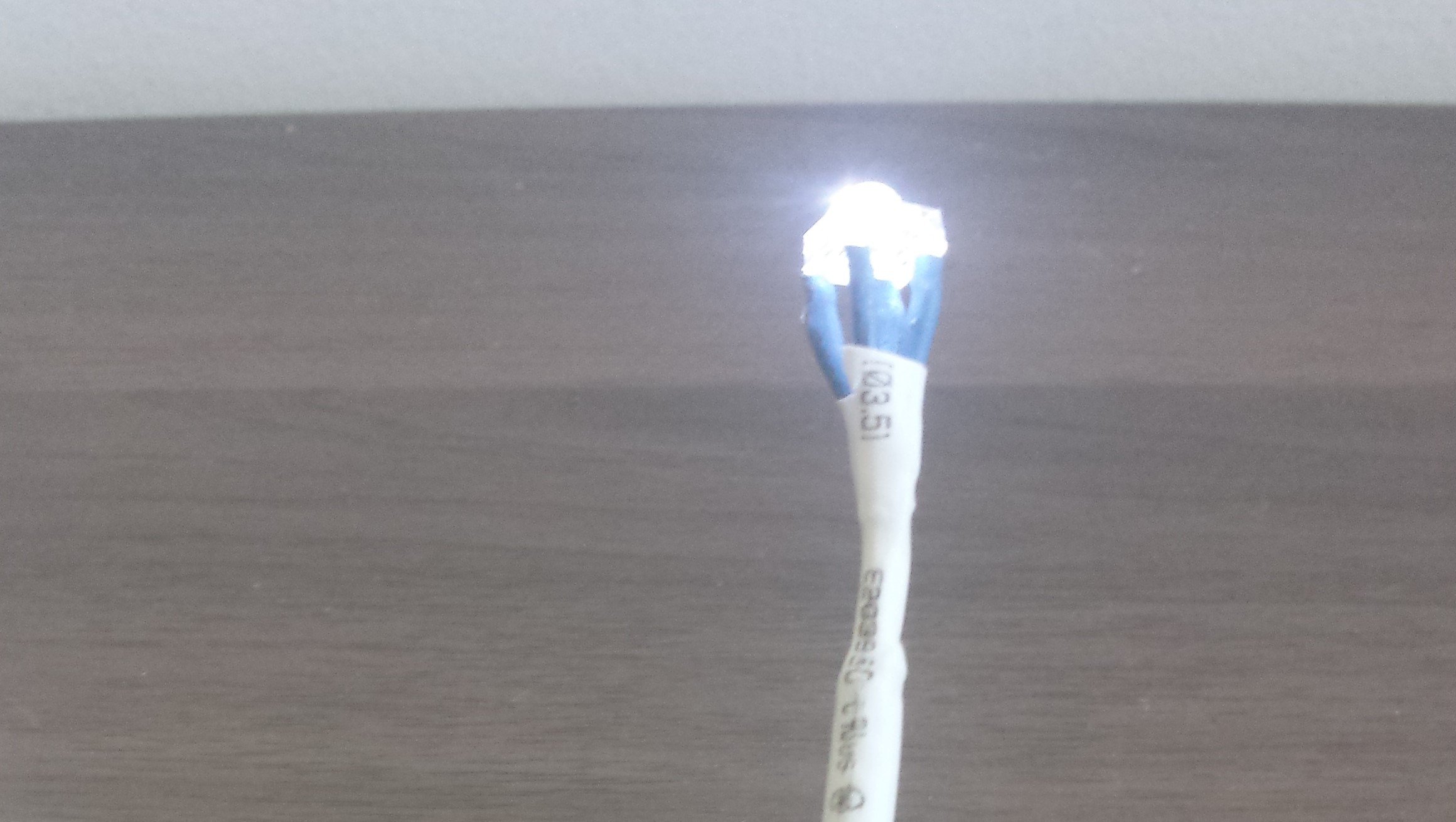
For these poles, I also tried out the LEDs. I used a couple different styles of lights. First, some quite bright (3000-4000mcd) and then some less bright (500-700mcd) ones. They both work well. I put three LEDs on the end of a USB cable (for shielding from the any conductance induced by the aluminum pole), but the shared ground did not work with the 1032 Phidget LED-64. As a result, I'll only have two LEDs on the top, which looks fine and still offers a reasonable brightness.
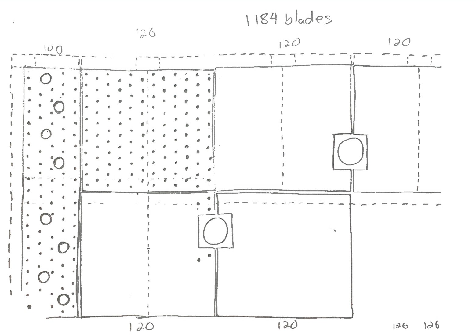
I've also laid out the board. The initial design was going to have 6 rotating boards, but after deciding to cut the motors, I can easily use one large 36″x72″ board. One benefit of the change is that it will allow more randomization of the grass blades, as there won't be a concern of them bumping into each other when they're swaying. Sensing movement will also be easier. With the motors, our plan was to use load cells installed on the lever extending from the motor shaft. The load cell would detect subtle compression and expansion as the blades moved the board. Without the motors, we'll use motion sensors, which are far easier to install.
I had to go back to the drawing board to redesign this beast. Pencil in hand, I got a new chassis laid out. I maintained most of the dimensions but forwent a lot of the support that had initially been intended for the motors.
Overall, I'm liking the changes. The new design will be far easier to weatherproof. One of my big concerns with the moving boards was having rain enter between the cracks and soak the electronics underneath. While there will still be points of entry, I'm optimistic about being able to use a silicone seal to prevent excessive seepage into the internal workings.
Part 4: How Does Your Garden Grow?
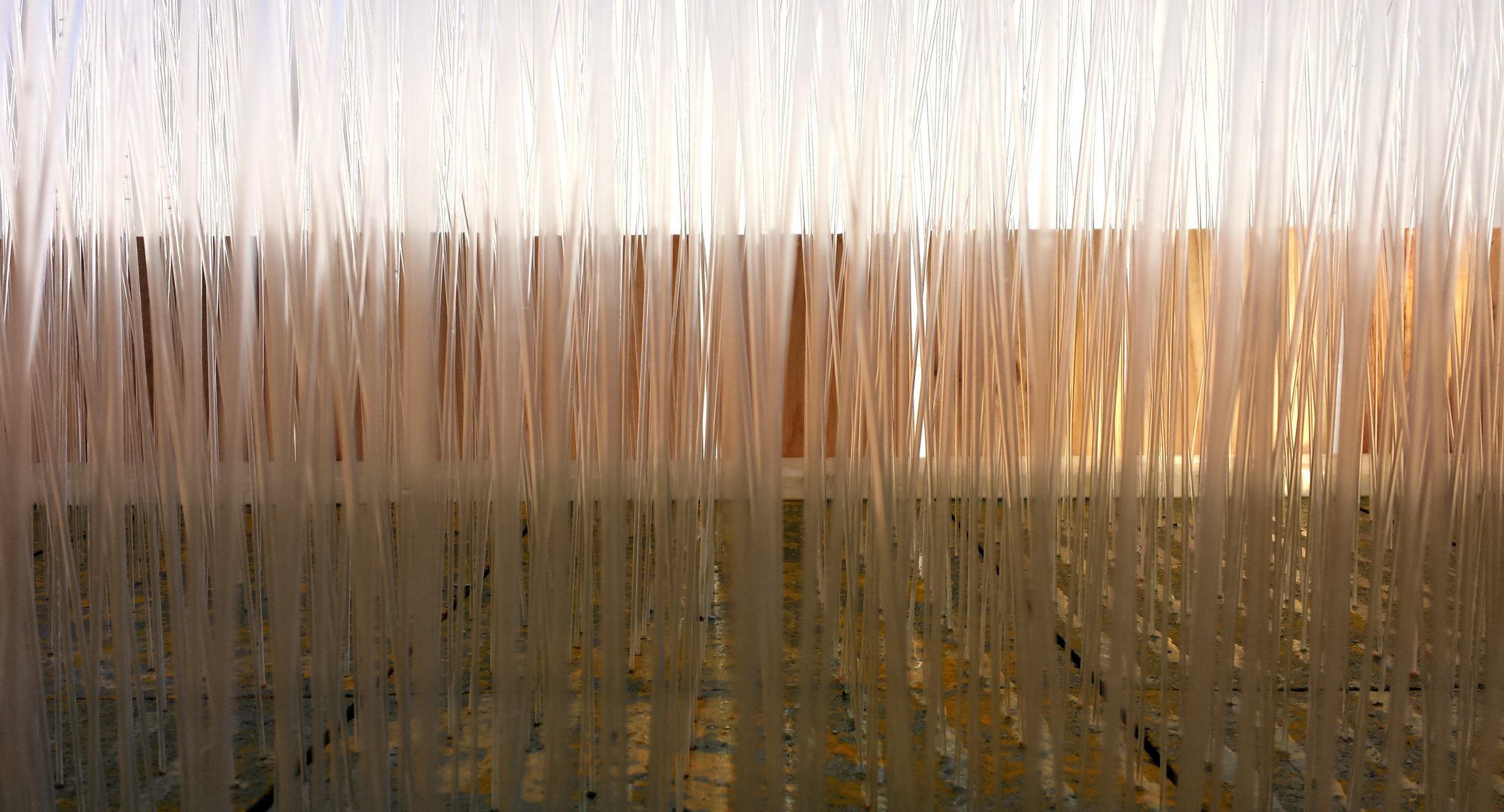
The interactive garden is finally starting to look like something impressive. With the base of the prototype built, I began hooking up the LEDs. I used the lights with an intensity of 3000-4000mcd and 1/16” diameter plexiglass rods. With the garden destined to be outdoors during the day, the brighter LEDs work a lot better. The 500-700mcd lights are difficult to see in a well-lit room, let alone in full daylight.
As you can see in the picture, the rods are quite bendy. I'll be trying out the 1/8″ rods later this week and see if they stay more erect, while still being able to carry the light up the entirety of the stem.
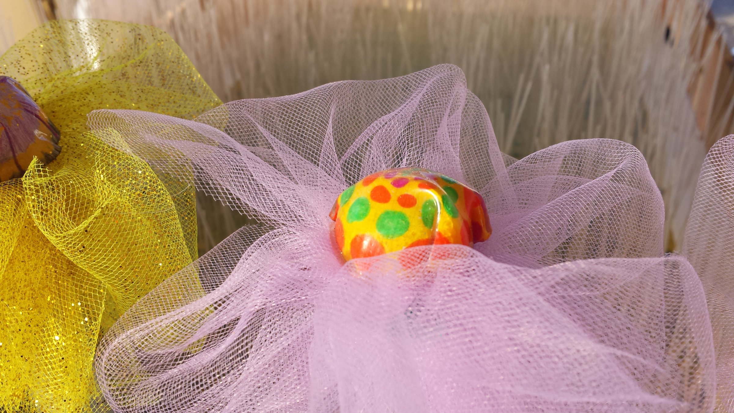
I created the “flower” with 2 feet of 1” diameter hollow aluminum rod, sparkly yellow tulle, green electrical tape and childhood's favourite art project, “Shrinky Dinks”. I was very pleased that the Shrinky Dinks I got from Michael's shrank to a good size. They are incredibly difficult to work with though. I'll need to experiment a bit more to figure out what method works best for getting them shaped as I want.
I sent the USB cable with two LEDs on the end (that I made last week) through the centre of the aluminum rod and affixed it to the top of the pole with electrical tape. I'll need to come up with a better solution for affixing the LEDs as it didn't take long before they had fallen down. I was going to add leaves to the “stem”, but I think that might be too crowded. I'll have to finish installing the remainder of the grass before making a decision on that.
I'm starting to realize what a time consuming and tedious process this is going to be in the next few weeks. I'm going to be focussing on getting down to business with building the real thing, and then writing some code to make it musical. But first, a bit more testing…
Part 5: The Garden Makes Sounds
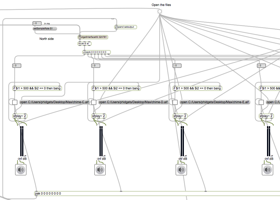
Although I don’t have too many updates for the interactive garden this week, I did get some work done on the sounds that will be made when touching the flour stalks and moving the grass. Right now, the sounds are just samples I found buried on my computer, but I expect to work on making the sounds more dynamic, distorted and interesting next week. The program, written in Max/MSP, will be easy to scale up once I add more sensors.
Unfortunately, the IR motion sensor is useless for detecting movement of non-heat radiating plexiglass. I will be trying some other alternatives next week, including a vibration sensor, force sensor and distance sensors.
Tracking down weathered fence boards and LEDs is going okay. I think I’ve got both secured, but need them to make them to me in good time, so fingers crossed. Overseas shipping is always risky and takes too long, but American products are more than twice the price, although they do (usually) arrive much quicker.
Part 6: Finding the Right Tools for the Garden
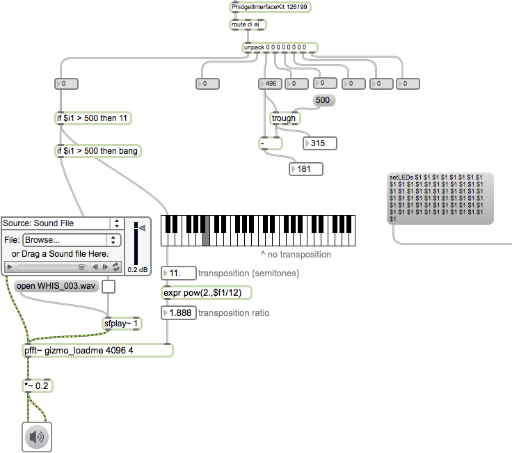
I ran some tests with different sensors and found the vibration sensor affixed to even just one of the plastic rods works great. Being affixed to the plywood board, it also seems able to pick up movement from the other rods as well. I had to play around with the Max 6 code. Right now I'm using a trough object, but I'd prefer something that calculates the rate of change in a given time window.
I'm still developing the sounds for the garden to be making. I've got a pitch-shifted bottle pipe sound for the large flower stalks now (but I'm having some problems having both the pitch shift and activation by touch) and hope to develop more wind chime sounds for the grass. The next programming challenge will be getting the lights to fade, rather than just turning off as they do now.
I finished calculating the lengths of wood, aluminum and plastic that I'll need. The most impressive number is 1250 yards of the plastic rod, which makes the 54 yards of 1×4″ and 2500 LEDs seem rather pale. I'll be picking up the lumber and supplies and start building the final design this weekend, and then I'll have plenty more fun pictures and stories to share.
Part 7: Priming and Painting the Garden
The clock is ticking to get the interactive garden up and running. So far, all tests have been really successful, and the parts for the final installation are coming together, but the LEDs and acrylic rod have yet to arrive, and that's a bit scary.
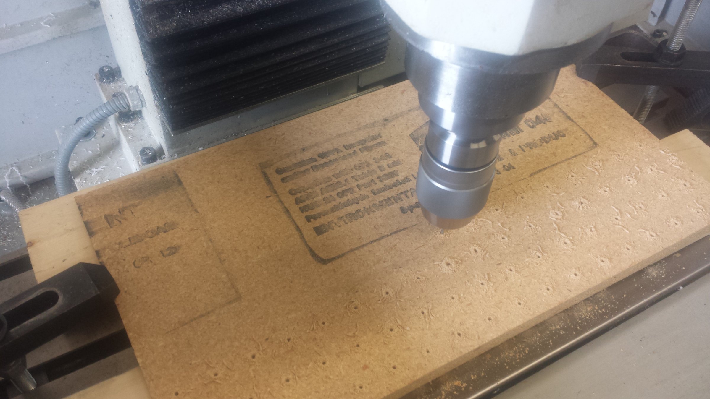
Instead of drilling each hole by hand, we'll be using a CNC machine. I figured out how to write a .pat file and gave it a try. After fixing a couple mistakes, it seems to do the job, although the plywood is prone to chipping on the reverse side. We'll run a test with the painted wood too see if the problem persists. We'll also try making sure the board is more flush with the supports underneath.

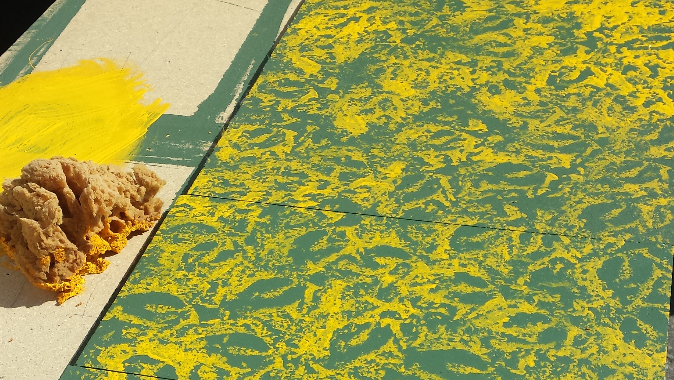
I painted the fourteen boards that we'll be using and drilling in the next week. Inspired by an interactive garden made by Guastovino, I hope to use moss on the base, but knowing that time is of the essence, I don't want to rely on it.
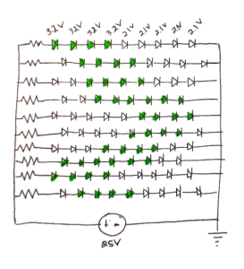
We've re-analysed the LED setup again, deciding to control squares of LEDS (probably about 40) at once. I didn't get the circuit diagram done yet, nor have I done any testing, but that will be happening this weekend, so stay tuned.
Finally, the colouring of the flower bulbs is also coming along. I printed off some pictures of flowers to trace onto the shrink plastic. They all look quite different and are tedious to make, but it's a nice result without having to pay too much. Related to the flower bulbs, I tried out a 3609 super flux LED for the light, and it works great. The beam is quite wide (90˚) and it's bright enough to light up the reasonably dark room I was testing it in. I almost wish I didn't have it hooked up to a computer at the time so I could use it to guide me around.
Part 8: Bringing it Together
Two weeks ago, serious construction of the interactive garden began. It was crunch time. Our 2450 LEDs had arrived, along with 3180′ of plexiglass rods. We got to work.
First, we drilled the holes in each board. We used a CNC machine to do the work. One of the wizards in the CNC machine's software helped provide a base for the program. I had to edit the file that the wizard generated to get it doing exactly what we wanted. After a few fixes, we got a file that did the trick. On the first pass, it drilled holes for the LEDs, about 1/4″ deep, in the wood. We then changed the drill bit and ran another pass, this time drilling all the way through the wood. Each run took about a half an hour so this consumed the entirety of one day.
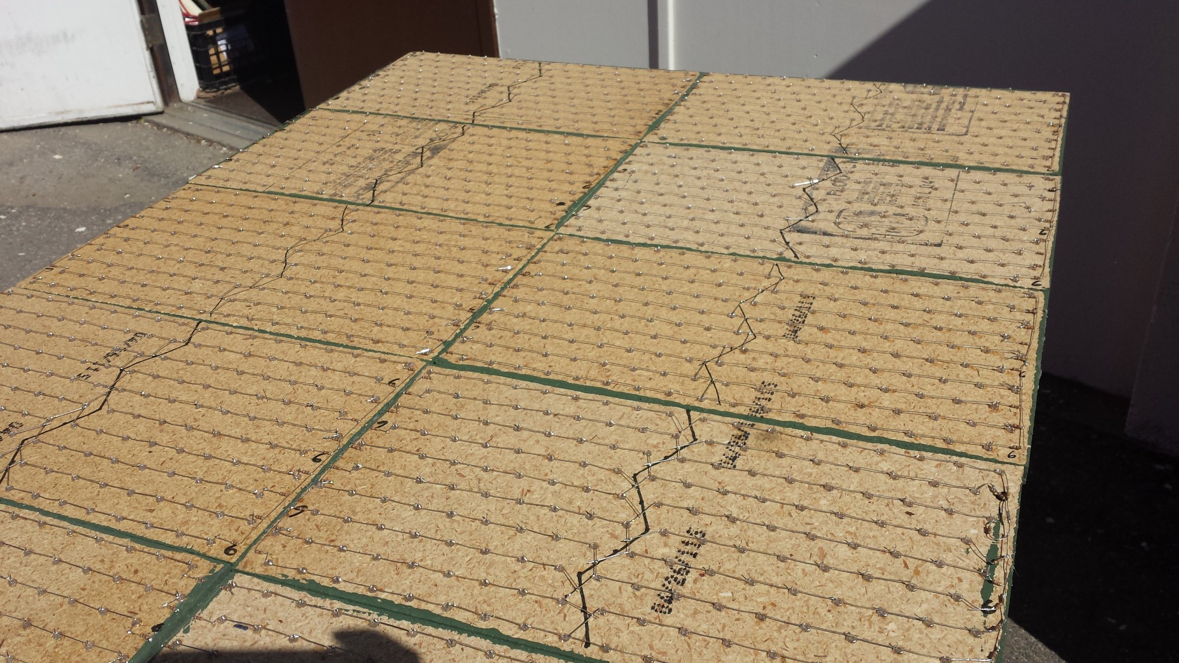
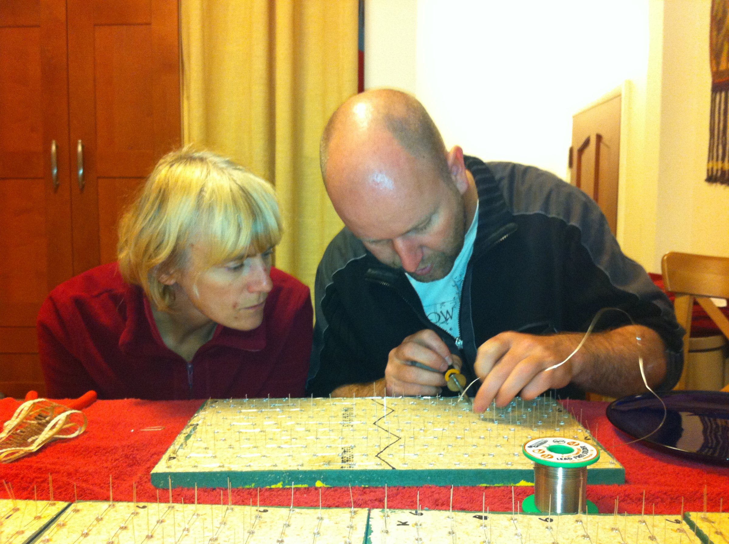
Once the holes were drilled, we placed the LEDs into the holes with a bit of silicone to hold them in place… and then waited for the silicone to set. Once the adhesive was dry, we were able to solder the LEDs together using this layout:
It was a lot of work, but we got it done.

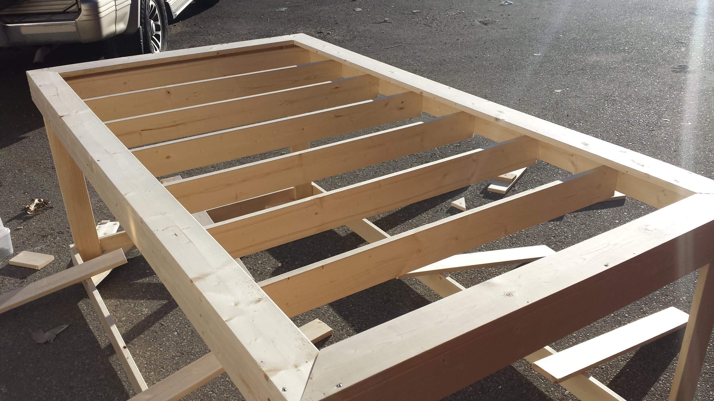
The next part to get working on was the frame. Chester came up with a lightweight design and got the wood. The LED boards we just finished would rest on the slats.
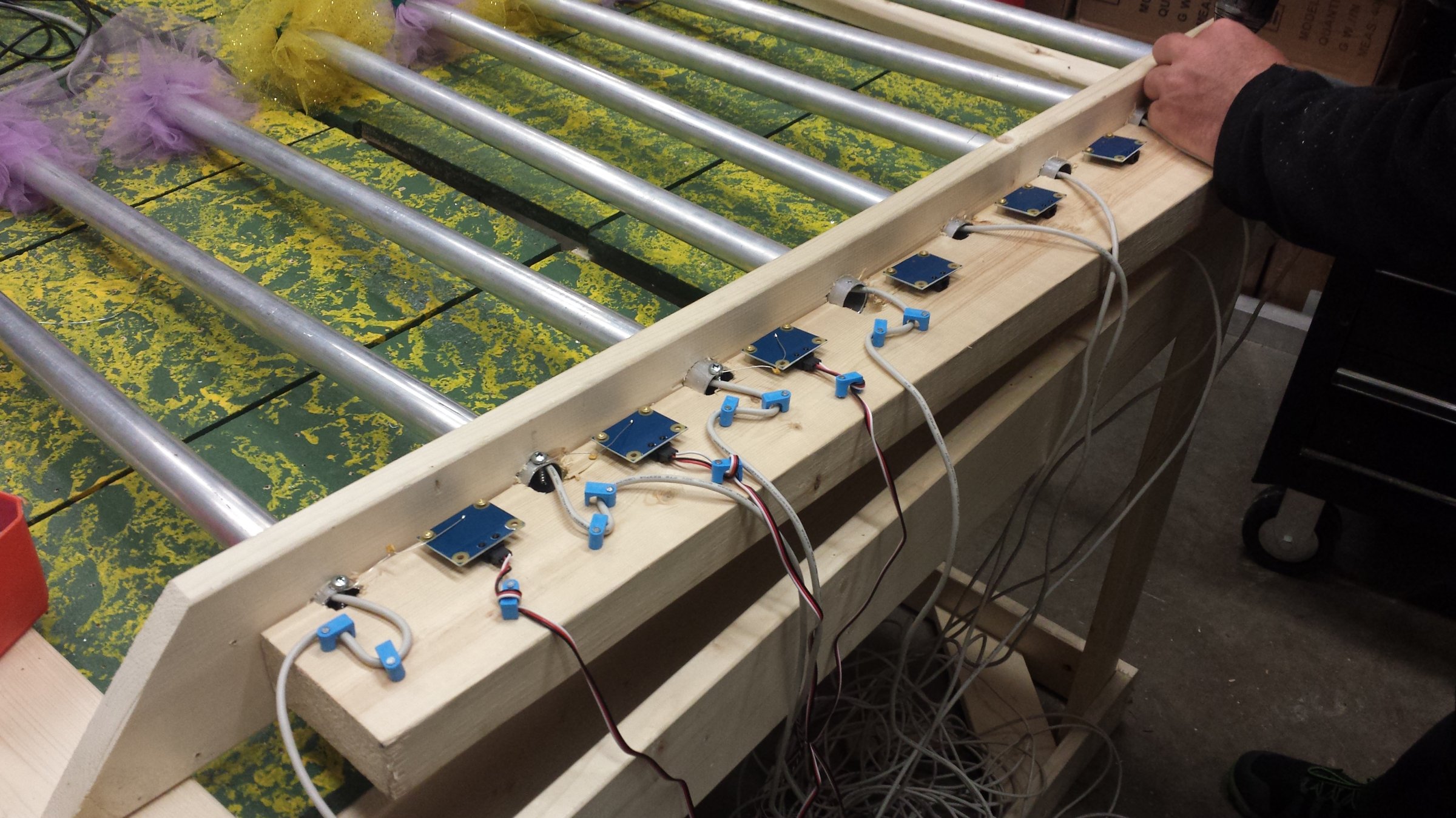
We moved on to work on the aluminum flowers that have touch sensors on the ends to trigger a note when they're touched. I'd already put together each rod with an LED affixed to the end of a USB cable, tulle, and a shrinkable plastic cap. On the wooden frame, we drilled eight holes. There's a 2×4″ length of wood underneath for support. Getting the holes the perfect size was difficult, but not impossible. We ended up using epoxy to secure the aluminum rods in the base. After that, we attached the touch sensor via a capacitor to the aluminum rod and plugged it into an interface kit. We put the LEDs into the digital outs of the same interface kit.
Next, it was more manual labour, cutting the plastic rods into 18″ pieces, placing them into the boards and affixing them with epoxy.
Vibration sensors were affixed to the bottom of each LED board as well. A special plexiglass rod was siliconed to each sensor so that we could ensure detection of motion. Once connected, each vibration sensor would need calibration as some picked up on very slight vibrations, while others required a lot more movement to send a signal.
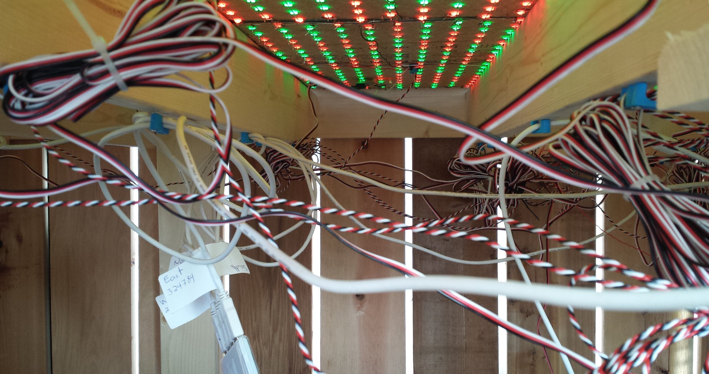
The final step was wiring everything up. Each block of LEDs was hooked to a power supply sending 28 volts of power to the circuit. The vibration sensors were connected to an interface kit, and all the kits were connected to a computer running the program written in Max6. For those keeping track, that's four interface kits, an LED controller, fourteen vibration sensors, sixteen touch sensors and a whole lot of LEDs.
We screwed on the fence boards and the job was done! We loaded it onto a truck and took it down to Beakerhead.
Part 9: The Show at Beakerhead
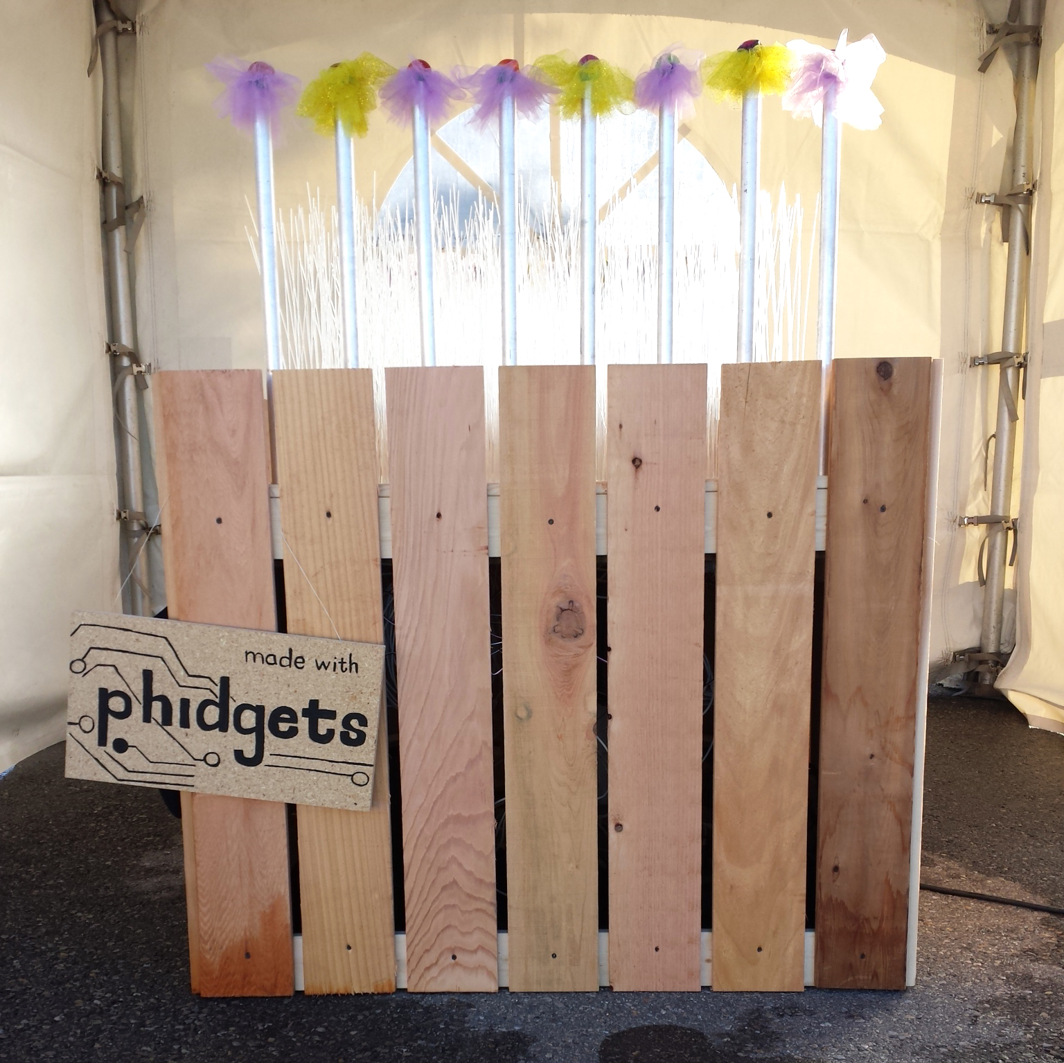
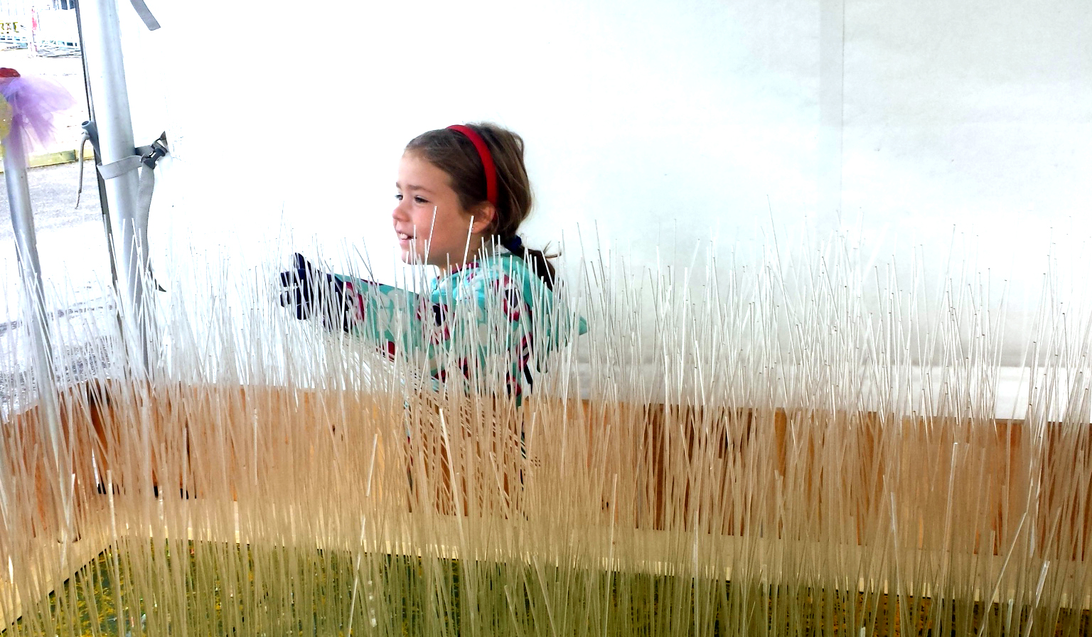
Because of an early snowfall hitting Calgary, the interactive garden rested a day before greeting the public on Thursday morning. School kids rushed in, running their hands through the plexiglass rods, smacking the aluminum flowers, and asking a ton of questions. The response was amazing.

As the day wore on, my fears of the computer program crashing were assuaged. Group after group were able to interact with the display, creating the sounds of chimes and bells with each hand swish and touch. Because the school groups arrived during the daytime, the light from the LEDs barely carried up the stems of the plastic “grass”.
Luckily, Beakernight gave us the opportunity to show off the garden in the dark, and it was a huge hit.
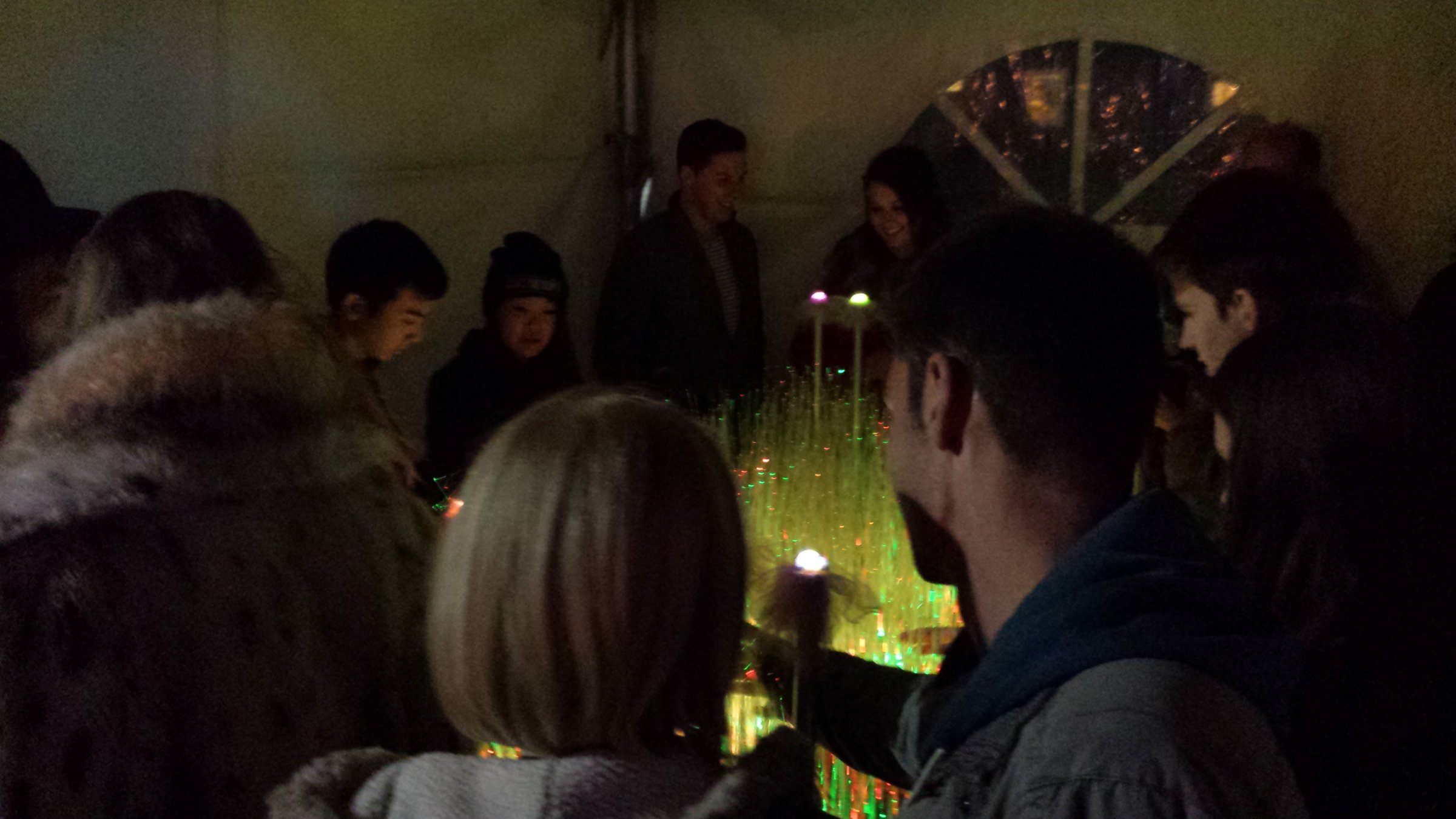
Lines of onlookers awaited to enter the tent that housed the display. People expressed how much they enjoyed the calm of the installation, and how neat it was to be able to interact with it. Some people even expressed interest in making something similar for Christmas.

A few visitors offered suggestions for sounds. One person wanted to hear a “moo” when they touched a certain section. Others thought it would be fun to do shrieks. On the last day, I reprogrammed the vibration sensors on the LED boards to respond with giggles and the flowers to respond with cries of pain. It was received with mixed results, but it did make more people laugh than the chimes and bells.
Many people coming by asked what something like this would be used for, what is its application? I usually threw the question back to the audience. People thought it could be used for burglar detection, or a door bell. Some people would use it as a halloween prank (with the shrieks or other spooky sounds). One lady even thought it would be great to put into a seniors' home or care facility, for people who enjoy tactile interaction and feedback.
Indeed, there's a lot of inspiration in this garden, as well as improvements moving forward.
One easy fix I'd implement right away is to make the flowers more playable. Right now, each sound must play out before being activated again. A number of people found this frustrating. I'd have to find a way in Max6 to layer the sound, but it shouldn't be too difficult to fix.
On an aesthetic level, I'd like to improve the appearance of the flowers, perhaps using metallic petals with glass bulbs instead of tulle and plastic. I think that would offer a more sturdy look to the design.
Some visitors inquired about how the garden was powered. While this version used a gas generator, it would be awesome to hook it up to a solar panel in future iterations.
The biggest problem with the display is the plexiglass rods that break very easily. Over the four days that the garden was out, over 100 of the plastic rods snapped or fell out, requiring me to pluck out the snapped piece from the hole (if possible), silicone the end of a new plexiglass rod, stick it in the hole, and wait for it to set. Because of the epoxy, some rods couldn't be removed from the board and so numerous bald patches dotted the board. Because the grass needs to remain erect, finding a material that is the perfect balance of flexibility and rigidity as well as unbreakable will be difficult.
Overall, the interactive garden was a great success, and hopefully you'll be seeing it out again soon!
Part 10: Frequently Asked Questions
You've seen the building process and the final result, but there's still more to say about the project. These are some of the common questions I got asked as visitors came around the garden and interacted with it. If you're wondering something, and the answer isn't here, please leave your question in the comments.
How does it work?
There are fourteen boards and each has a vibration sensor attached to the bottom. Each vibration sensor has a single blade of plexiglass glued to it. When that piece of “grass” moves, the vibration sensor reads its vibration. The Phidget interface kit converts the analog signal to a digital signal and sends the value into a MAX6 program.
In the program we scale the input so it reads between 0 and 1. This value is used to set the brightness of the light, so the more vibration, the brighter the light. When the value is over 0.5, a bell chime sound is triggered.
There are sixteen capacitive touch sensors, one on the end of each aluminum pole. When someone touches the pole, the capacitance changes and the sensor/interface kit sends a signal of about 1000 to the program. When this happens, a chime sound is triggered. Along with this, the LED connected to the interface kit's digital output is switched on.
How come not every grass blade responds?
Vibration sensors are used to detect vibrations, and they're connected to one rod near the edge of each LED board. Vibration sensors are about 2 inches by 1 inch, and they're not cheap enough to put 175 of them on each piece of grass. Besides, the programming would get a little intense at that point.
Where do the sounds come from?
The sounds are coded into the MAX6 program. When the sensors hit a certain value, they trigger a sound.
Is it fibre optics?
No. Optical fibre is more transmissive than the plexiglass we're using, it's also thinner, and more expensive. Because the lengths of plexiglass rod are quite short (18 inches), they are able to carry the light as we need.
Who made this?
Me, Kat Dornian, with a lot of help. I came up with the idea. Chester (Phidget CEO) helped a lot with the design and construction, along with other hands here and there.
How long did it take to make?
It probably took about 135 hours, or about 3 solid work weeks for one person. I've been planning this for nearly 6 months though, with work here and there.
How is it powered?
We used a regular power supply this year, but maybe next time we'll hook up some solar panels.
What is it used for?
The design came out of a challenge to use MAX6 with Phidgets, and, I thought, why not make something cool for Beakerhead while we're at it? So, I came up with something very interactive and eye-catching. It's mostly just decorative, not intended for anything in particular, but hopefully it inspires some people to make something cool.