Current Sense Resistors
How to set up a current sensor for use with a VCP1002.
by James

Introduction
In many applications it is desirable to measure the current supplied to a load to monitor and control power consumption of the system.
Current sense resistors are a common, simple, and inexpensive way to measure current in a circuit. They are placed in series with a load, where current flowing through the branch will generate a voltage across the resistor. This voltage can then be measured, and the current determined using Ohm's law (I=V/R). Current sense resistors are useful in low-current applications where indirect methods like hall-effect sensors may be too costly.
Hardware
Selecting a Current Sense Resistor
When selecting a current sense resistor, it is important to minimize the resistance in order to limit losses and self-heating of the resistor. The trade-off for minimizing the resistor is that by shrinking the resistance, the voltage drop across it will shrink too, which in turn affects the resolution of the measurement.
There are a number of ways to select an appropriate current sense resistor. Here we will focus on selecting an optimal resistor for use with the VCP1002 Small Voltage Sensor.
Since the VCP1002 has fixed input ranges, it is recommended to select a resistor that will produce a voltage drop close to one of these ranges at the peak current draw of the load. Here we will design to make use of 90% of the 40mV mode, to ensure good resolution while avoiding saturation.
To make this calculation, one must know the expected peak current draw of the system (\(I_{max}\)). With that, calculating the optimal resistor is a simple as dividing the maximum tolerable voltage drop across the current sense resistor (\(V_{drop}\)) by the maximum current. For the following example we'll assume out maximum current to be 2A. Using the 40mV mode, \(V_{range}\) will be 40mV.
$$I_{max}=2\mathrm A$$ $$V_{drop} \le 0.9\cdot V_{range}$$ $$V_{drop} \le 0.036\mathrm V$$ $$R_{sense} = V_{drop} / I_{max}$$ $$R_{sense} \le 0.018\Omega$$
Once a resistor value has been calculated, an appropriate resistor may be selected. The resistance of the chosen resistor should not exceed the calculated value in order to avoid saturating the sensor.
As a final note, it is prudent to verify the power rating of the resistor to ensure it can handle the currents expected to flow through it. This can be checked using the following power equation.
$$P_{rated} > I_{max}^2\cdot R_{sense}$$Current Sense Resistor Placement
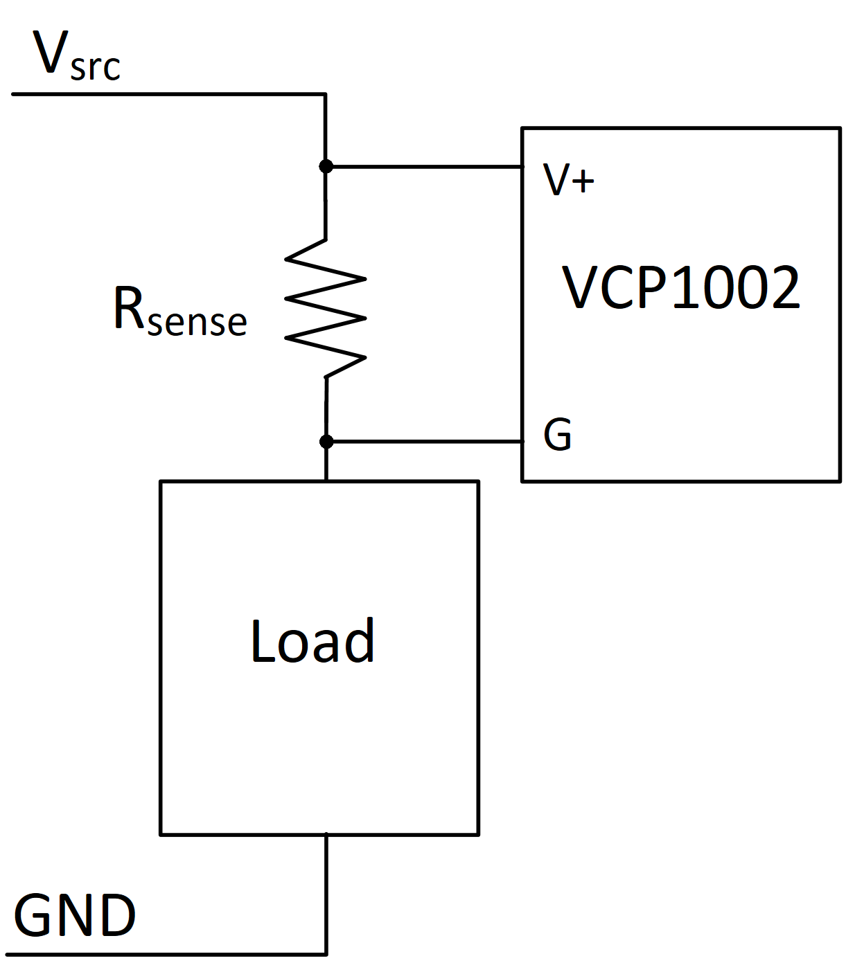
When using a Phidget VCP1002 for measuring a current sense resistor, it is recommended to position the resistor on the high-side of the load, as seen below. The VCP1002 is isolated and will accurately measure the drop across the current sense resistor regardless of the common-mode offset. This will prevent grounding problems that arise when placing the resistor on the low-side.
Software
To set up the VCP1002 for use with a current sense resistor, first set the VoltageRange of the sensor to that which was used when selecting the resistor. This may be done after opening the device, or as part of the VCP1002's attach event handler.
Once set up, the VCP1002 will start reporting the voltage across the current sense resistor, from which the current is calculated.
static void CCONV
onVoltageChangeHandler(PhidgetVoltageInputHandle ch, void *ctx, double voltage) {
	double resistance = 0.1; //resistance in ohms
	double current = voltage / resistance;
	printf("Current Changed: %.5f\n", current);
}
Conclusion
Current sense resistors are a simple method for measuring small currents in a wide variety of low current applications. The design and use of such systems can be simplified further by using a VCP1002 Small Voltage Sensor to reliably measure the small voltage across a current sense resistor to calculate the current.