Making a Chain Counter
by Brian

Introduction
We sell #25 and #40 chain by the meter for use with our array of sprockets. The chain comes from the factory on large reels which makes it fairly easy to unravel once you mount it on an axel of some kind. Using a measuring tape to measure out a meter or two is annoying but manageable. For longer lengths though it is just impractical. To that end I wanted to put together a little mechanism that could count the chain out so our shippers could pick orders with chain more efficiently. All it would need to consist of was a free spinning sprocket, an encoder, and some way to display the count.
Assembly
We currently have the #25 and #40 reels mounted directly next to each other on separate 25mm bearings. I'd like to be able to slot this counter into the existing system. It's far easier to move the counter than the heavy reels, and the counter needs to be able to service both reels so it will need to be adjustable. I can mount the counter on a sliding rail so that it can change reels easily as well as move with the chain as it spools back and forth across each individual reel. I'm going to use 2 12mm rails as the track and then make a carriage out of 2 pieces of angle iron mounted to a pair of linear bearings each. A rough idea of what I am aiming for is the following:
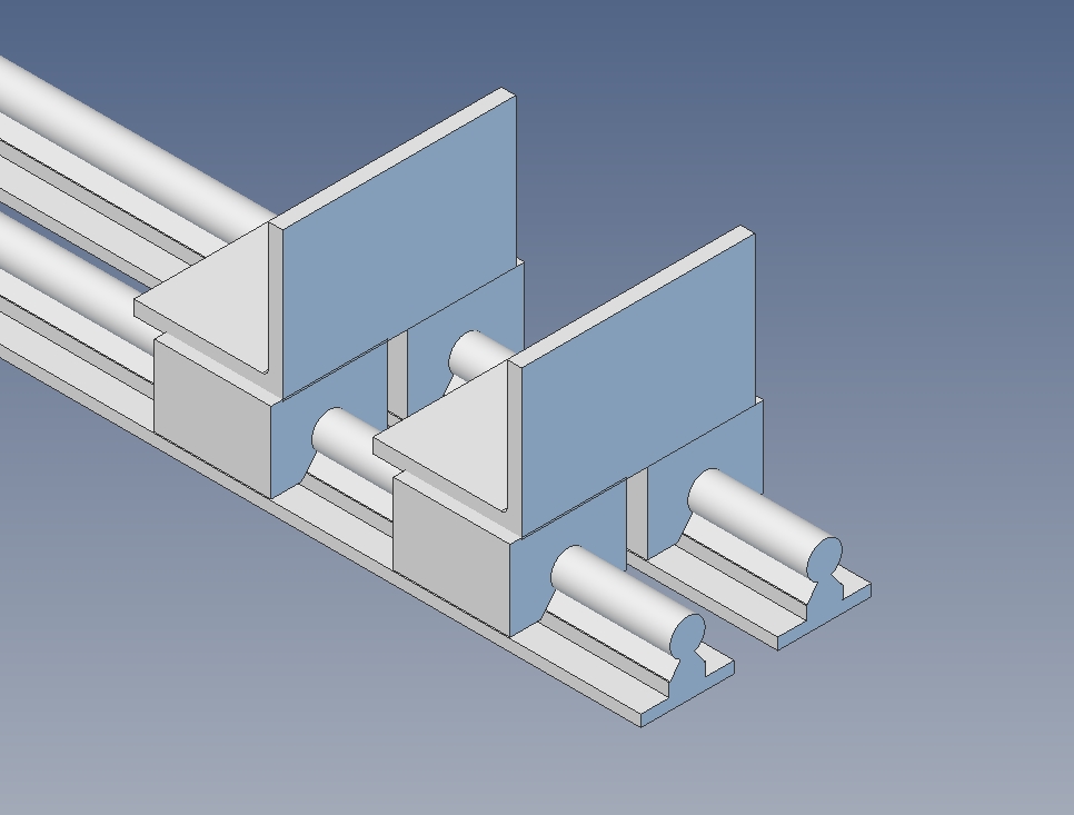
Then I can just mount a few flange bearings onto the angle iron and put a shaft through it to support the 2 sprockets required. With the mechanical components out of the way I can attach an encoder and the main counter assembly is done. Here is the finished counter:
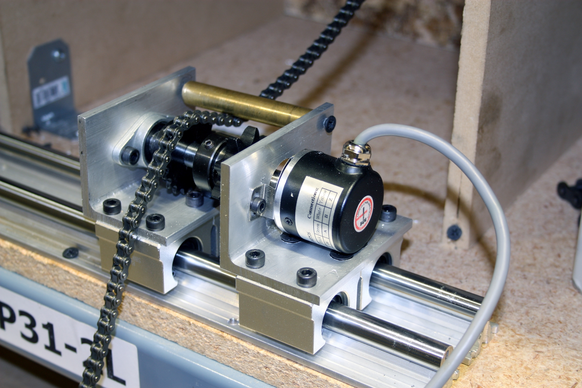
I ended up using 8mm shaft since the 3532 Hollow Shaft Encoder has an 8mm bore and that just simplifies the construction. Also, note the brass tube at the top of the angle iron. I found that the chain wasn't settling on the sprockets very well when operated with a natural pulling motion. You had to sort of pull out and down to keep it seated. I stuck the tube on there as a form of guide to keep the chain seated when pulling more normally. It makes initial set up slightly more time consuming but overall it is a significant improvement.
Electronics
For the electronics side of this I am going to need an encoder interface and a screen of some kind to display the measurements. There is no computer situated near the chain rack so I will need to drive this off an SBC. All told I am going to be using a 1057, 1073 and a 1203. We begin by defining our encoder resolution and sprocket sizes, and then creating global handles for all the necessary objects:
#define CPR 1440
#define SMALLTOOTHCOUNT 18
#define BIGTOOTHCOUNT 9

//Declare handles
PhidgetDigitalInputHandle operatorInput;
PhidgetLCDHandle display;
PhidgetEncoderHandle sprocket;

// Global variables
int state = 0; //0 = #25, 1 = #40
double chainLength = 0.0;
All Phidgets have attach, detach, and error event handlers which can be set up. The important bits though are the handlers which are unique to each device, where the actual data processing will be handled. First I'll create objects and assign them to my global handles, and then assign data handlers to them:
int main(int argc, char **argv) {

        const char *err;
        PhidgetReturnCode result;

        //create objects
        PhidgetDigitalInput_create(&operatorInput);
        PhidgetLCD_create(&display);
        PhidgetEncoder_create(&sprocket);

        // register data handlers
        PhidgetDigitalInput_setOnStateChangeHandler(operatorInput, InputChangeHandler, NULL); //mode switching
        PhidgetEncoder_setOnPositionChangeHandler(sprocket, PositionChangeHandler, NULL); //chain unspooling
The input change handler will read input from the switch I will use to toggle between #25 mode and #40 mode. I will need different modes since the chains have different pitches and the sprockets I am using have different numbers of teeth. Consequently there will need to be a different conversion formula applied to convert from encoder ticks to chain length. The position change handler will deal with the encoder tick events and use them to calculate the length of the chain. Before we open the device channels, we need to set some properties:
         Phidget_setDeviceSerialNumber(display, 120212);       // 1203_2 - PhidgetInterfaceKit w/LCD
         Phidget_setDeviceSerialNumber(operatorInput, 120212); // 1203_2 - PhidgetInterfaceKit w/LCD
         Phidget_setDeviceSerialNumber(sprocket, 102246);      // 1057_2 - PhidgetEncoder
         Phidget_setChannel(operatorInput, 0);                 // Channel 0 on the 1203_2
Setting the serial number ensures that I'm opening the correct Phidget, and setting the channel ensures I'm opening the correct digital input on that Phidget. Now I can open each channel, with error-checking in case something goes wrong:
        if (result = Phidget_openWaitForAttachment((PhidgetHandle)display, 10000))
        {
            Phidget_getErrorDescription(result, &err);
            printf("Problem waiting for LCD attachment: %s\n", err);
            return 1;
        }

        if (result = Phidget_openWaitForAttachment((PhidgetHandle)operatorInput, 10000))
        {
            Phidget_getErrorDescription(result, &err);
            printf("Problem waiting for DigitalInput attachment: %s\n", err);
            return 1;
        }

        if (result = Phidget_openWaitForAttachment((PhidgetHandle)sprocket, 10000))
        {
            Phidget_getErrorDescription(result, &err);
            printf("Problem waiting for Encoder attachment: %s\n", err);
            return 1;
        }

        initializeDisplay(display);

        while (1) {
            Sleep(1000);
        }
The initializeDisplay subroutine is then called in order to set the screen size and brightness, in addition to displaying the chain size and length. After that, the program will just loop infinitely while encoder and digital input events come in. Here's what the initializeDisplay function looks like:
static void initializeDisplay(PhidgetLCDHandle display) {

    char buffer[50];

    PhidgetLCD_setScreenSize(display, SCREEN_SIZE_2x20);
    PhidgetLCD_setBacklight(display, 1);
    PhidgetLCD_writeText(display, FONT_5x8, 0, 0, state ? "Chain type: #40" : "Chain type: #25");

    snprintf(buffer, 50, "Length: %.2f cm", chainLength);
    PhidgetLCD_writeText(display, FONT_5x8, 0, 1, buffer);
    PhidgetLCD_flush(display);
}
Finally, here is the code for the two event handlers, where this program will be spending the majority of its time:
static void CCONV
InputChangeHandler(PhidgetDigitalInputHandle operatorInput, void *ctx, int State) {

    char buffer[50];

    state = State; //set the global state, 0=#25, 1=#40
    PhidgetLCD_writeText(display, FONT_5x8, 0, 0, state ? "Chain type: #40" : "Chain type: #25");
    chainLength = 0;
    snprintf(buffer, 50, "Length: %.2f cm", chainLength);
    PhidgetLCD_writeText(display, FONT_5x8, 0, 1, buffer);
    PhidgetLCD_flush(display);
}
static void CCONV
PositionChangeHandler(PhidgetEncoderHandle ch, void *ctx, int positionChange, double timeChange, int indexTriggered) {

    char buffer[50];

    if (state)	//#25 chain = 0.25" pitch
	{
		//                     ticks           /  cycles/rev   /  ticks/cycle  *   teeth/rev   * inches/tooth / inches/m * cm/m
		chainLength += ((double)positionChange /     CPR       /       4       * BIGTOOTHCOUNT *      0.5     / 39.3701  * 100);
	}
	else if (!state)
	{
		//                     ticks           /  cycles/rev   /  ticks/cycle  *   teeth/rev     * inches/tooth / inches/m * cm/m
		chainLength += ((double)positionChange /     CPR       /       4       * SMALLTOOTHCOUNT *     0.25     /  39.3701 * 100);
	}
    snprintf(buffer, 50, "Length: %.2f cm", chainLength);
    PhidgetLCD_writeText(display, FONT_5x8, 0, 1, buffer);
    PhidgetLCD_flush(display);
}
And with that we are done. Simple. All the electronics are mounted in a project box (BOX4205). I cut a few panels out for the power switch, mode switch, LCD screen, and a hole for the power cable and encoder cable which are supported by a strain relief nipple (CBL4400). So, how does it work?