3618 User Guide
From Phidgets Support
| |
| Go to this device's product page |
Introduction
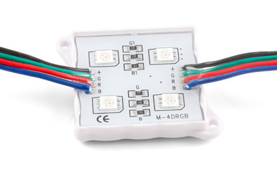
This manual describes how to connect and control the 3618 LED module using Phidgets I/O boards and relays.
I/O Boards:
Relays:
Connecting the LED Module
Connecting to the REL1100 or REL1101
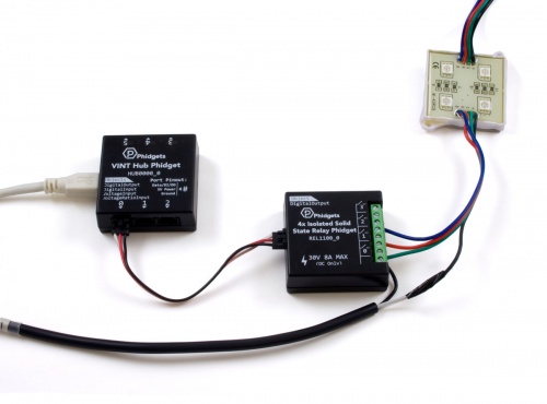
- Connect the ground (-) wire from your power supply to one of the ground terminals on the Phidget.
- Connect the black anode wire from the LED module to the power supply live wire (+).
- Connect the red, blue, and green cathode wires from the RGB module to the numbered terminals on the Phidget.
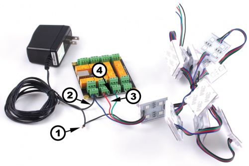
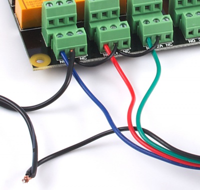
Connecting to the 1012 - PhidgetInterfaceKit 0/16/16
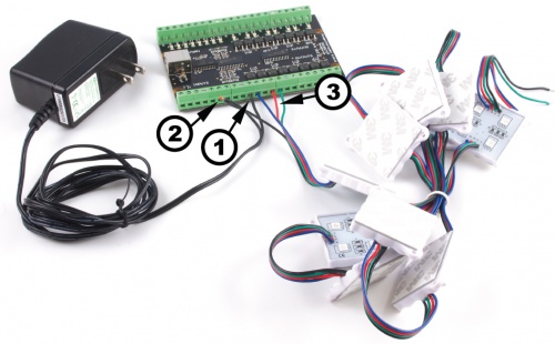
Note: Be aware that the LEDs can get damaged if the proper polarity is not respected: Anode (+), Cathode (-). |
| |
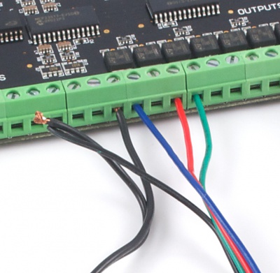
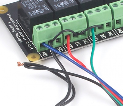
Connecting to the 1014 - PhidgetInterfaceKit 0/0/4
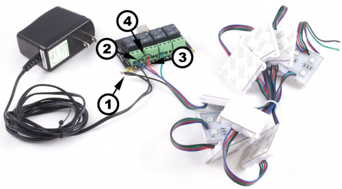
If you connect the power supply live wire to the NC (Normally Closed) terminal, the LED strip will be ON when the switch is off. Note: Be aware that the LEDs can get damaged if the proper polarity is not respected: Anode (+), Cathode (-). |
| |
Connecting to the 1017 - PhidgetInterfaceKit 0/0/8
Note: Be aware that the LEDs can get damaged if the proper polarity is not respected: Anode (+), Cathode (-). |
| |