Template:UGC-NonPhidgetSensor
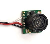
If the sensor requires 5V DC power and outputs a 0-5V signal, you can connect it directly to a VINT Port. The easiest way to connect it is to cut the end off of a Phidget Cable and solder the bare wires to the appropriate pins:
- Black: Ground
- Red: 5V Power
- White: 0-5V Analog Signal
You should check the sensor's datasheet to determine if it is Ratiometric or Non-Ratiometric. Ratiometric sensors output a voltage proportional to the voltage on the 5V power line, so they're more resilient against noise and power fluctuations. Non-Ratiometric sensors have their own 5V regulator, and always output a voltage relative to that 5V reference point. You need to use the appropriate channel class when opening the sensor (i.e. the VoltageRatioInput class or the VoltageInput class), or else your sensor readings will be inaccurate.
You can tell a sensor is ratiometric if the output in the datasheet is specified in units of volts-per-volt (V/V) or in terms of its supply voltage ("Vcc"):
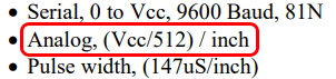
This specification says the sensor outputs a voltage value of Vcc/512 for each inch of measurement, so it must be ratiometric.
First, check how the sensor communicates:
- If it provides a 0-5V signal proportional to the measured value, it can be connected directly to the white wire of the Phidget Cable.
- If it outputs a 4-20mA signal, you can use the DAQ1400, and then connect that to your VINT Hub.
- If it outputs an NPN, PNP or pulse signal, you can also use the DAQ1400.
- If it uses Serial or I2C communication, it can't easily be connected to the VINT Hub.
Next, check how much power the sensor requires:
- If it requires 5V DC, you can use the red wire of the Phidget Cable directly
- If it requires 12V or 24V DC, you can use the DAQ1400
- If it requires higher power, you'll need an external power supply. In this case, ensure the VINT Hub ground is connected to the external power supply ground for better stability.