Template:VINTTable
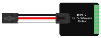
VINT Device Mode
This mode is for connecting to a VINT device. These devices differ from analog sensors because instead of just reporting 0 to 5 volts, they communicate with the VINT Hub. The communication is digital, therefore it is immune to electrical interference between the hub and the device. | |
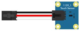
Digital Input Mode
In digital input mode, the VINT Hub port can act as an active-low digital input. This mode is great for reading the state of buttons and switches. |
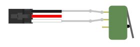
Voltage Ratio Input Mode
In voltage ratio input mode, the VINT Hub port will read the voltage on the white wire and compare it to the voltage being supplied on the red wire. This mode will let you read any ratiometric Phidgets sensor. |
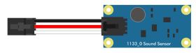
Voltage Input Mode
In voltage input mode, the VINT Hub port will read the voltage on the white wire. This can be used to interface a non-ratiometric sensor, or to measure the voltage in a 5V digital circuit. |
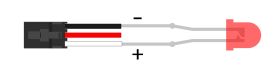
Digital Output Mode
In digital output mode, a VINT Hub port can behave like a 3.3V digital output. You could use this mode to blink an LED or switch on a MOSFET. And don't worry if you still need a 5V digital output; there are VINT modules available that provide multiple 5V digital outputs on a single VINT port. |