|
|
| Line 1: |
Line 1: |
| [[Category:UserGuide]] | | [[Category:UserGuide]] |
| {{UserguideTOC|1044.jpg|1044}}
| |
|
| |
|
| ==Getting Started== | | ===Required Hardware=== |
|
| |
|
| ===Checking the Contents===
| | * A 1044 Spatial Phidget |
| {{UGbox|
| | * A USB Cable |
| '''You should have received:'''
| | * A computer |
| * A PhidgetSpatial 3/3/3 High Resolution | |
| * A Mini-B USB cable | |
| |||}}
| |
|
| |
|
| ===Connecting the Pieces=== | | ===Connecting the Pieces=== |
| {{UGbox|
| | [[Image:1044_Functional.jpg|300px|right|link=]] |
| Connect the PhidgetSpatial 3/3/3 to your PC using the Mini-B USB cable.
| | # Connect your device to your computer using the USB cable. |
| |
| |
| [[File:1056_0_Connecting_The_Hardware.jpg|400px|link=]] | |
| ||}}
| |
|
| |
|
| ===Testing Using Windows 2000 / XP / Vista / 7=== | | <br clear="all"> |
| | ==Testing Using Windows== |
|
| |
|
| {{UGwin}} | | {{UGcontrolpanel|1044}} |
|
| |
|
| ===Running Phidgets Sample Program===
| | {{ugAccelerometer}} |
|
| |
|
| {{UGwin2|'''Spatial-full'''}} | | {{ugGyroscope}} |
|
| |
|
| {{UGbox| | | {{ugMagnetometer}} |
| Double Click on the [[File:Ph.jpg|link=]] icon to activate the Phidget Control Panel and make sure that the '''Phidget Spatial 3/3/3''' is properly attached to your PC.
| |
| |[[File:1042_0_Control_Panel.jpg|400px|link=]]
| |
| |
| |
| # Double Click on '''Phidget Spatial 3/3/3''' in the Phidget Control Panel to bring up Spatial-full and check that the box labelled Attached contains the word True.
| |
| # You can adjust the Data Rate by moving the slider.
| |
| # Move the 1044 board around and you should see the data change to reflect the change of position along the 3 axes.
| |
| |[[File:1042_0_Spatial_Screen.jpg|400px|link=]]
| |
| }} | |
|
| |
|
| ===Testing Using Mac OS X===
| | {{ugSpatial}} |
|
| |
|
| {{UGmac|Phidget Spatial 3/3/3|Spatial-full}} | | {{UGotheros}} |
| | |
| ===Using Linux===
| |
| | |
| {{UGlinux}}
| |
| | |
| ===Using Windows Mobile / CE 5.0 / CE 6.0===
| |
| | |
| {{UGce}}
| |
|
| |
|
| ==Technical Details== | | ==Technical Details== |
| Line 78: |
Line 56: |
| For more information on magnetometers (compasses), see the [[Compass Primer]]. | | For more information on magnetometers (compasses), see the [[Compass Primer]]. |
|
| |
|
| ==API==
| | {{UGnext|}} |
| {{UGapih}} | |
| | |
| ===Data Structures===
| |
| <b>
| |
| SpatialData {
| |
| :double acceleration[3];
| |
| :double angularRate[3];
| |
| :double magneticField[3];
| |
| :Timestamp time;
| |
| };
| |
| | |
| Timestamp {
| |
| :int seconds; -time since attach event
| |
| :int microseconds; -time since last second
| |
| };
| |
| </b>
| |
| | |
| The SpatialData Structure is used by the OnSpatialData event. This contains acceleration data, angular rate data, magnetic field data, and a timestamp. The timestamp is an accurate measurement streamed from the hardware,and can be trusted over a local software timestamp. This timestamp is generally used for integrating angular rate into a heading over time.
| |
| | |
| ===Properties===
| |
| {{UGapi|int AccelerationAxisCount() [get] : Constant <nowiki>=</nowiki> 3
| |
| |Returns the number of axes the PhidgetSpatial can measure acceleration on.
| |
| }}
| |
| | |
| {{UGapi|double Acceleration (int AxisIndex) [get] : Units <nowiki>=</nowiki> g (standard gravity <nowiki>=</nowiki> 9.81m/s2)
| |
| |Returns the acceleration of an axis. At a standstill each axis will measure between -1.0 and 1.0 g’s depending on orientation - the effect of gravity.
| |
| This value will always be between AccelerationMin and AccelerationMax.
| |
| }}
| |
| | |
| {{UGapi|double AccelerationMax (int AxisIndex) [get] : Constant <nowiki>=</nowiki> 8.1g
| |
| |Returns the maximum acceleration value that this axis will report. Acceleration can be accurately measured up to 8.0g - any value past this will be reported as 8.1g, which represents saturation. If the acceleration data is equal to AccelerationMax, it should be treated as suspect, as the real acceleration could be far greater than the reported number.
| |
| }}
| |
| | |
| {{UGapi|double AccelerationMin (int AxisIndex) [get] : Constant <nowiki>=</nowiki> -8.1g
| |
| |Returns the maximum negative acceleration value that this axis will report. Negative acceleration can be accurately measured up to -8.0g - any value past this will be reported as -8.1g, which represents saturation. If the acceleration data is equal to AccelerationMin, it should be treated as suspect, as the real acceleration could be far greater than the reported number.
| |
| }}
| |
| | |
| {{UGapi|int GyroAxisCount() [get] : Constant <nowiki>=</nowiki> 3
| |
| |Returns the number of axes the PhidgetSpatial can measure angular momentum on.
| |
| }}
| |
| | |
| {{UGapi|int AngularRate(int AxisIndex) [get] : Units <nowiki>=</nowiki> °/s (degrees/second)
| |
| |Returns the angular momentum on an axis. This value will always be between AngularRateMax and AngularRateMin. If the value is equal to AngularRateMax or Min, the data should be treated as suspect, as the sensor may be saturated.
| |
| }}
| |
| | |
| {{UGapi|int AngularRateMax(int AxisIndex) [get] : Constant <nowiki>=</nowiki> 2000°/s
| |
| |Returns the maximum angular momentum that this axis will report. If the angular rate is reported as 2000°/s, this should be considered saturated, and any heading integration will have errors.
| |
| }}
| |
| | |
| {{UGapi|int AngularRateMin(int AxisIndex) [get] : Constant <nowiki>=</nowiki> -2000°/s
| |
| |Returns the maximum negative angular momentum that this axis will report. If the angular rate is reported as -2000°/s, this should be considered saturated, and any heading integration will have errors.
| |
| }}
| |
| | |
| {{UGapi|int CompassAxisCount() [get] : Constant <nowiki>=</nowiki> 3
| |
| |Returns the number of axes the PhidgetSpatial can measure magnetic field strength on.
| |
| }}
| |
| | |
| {{UGapi|int MagneticField(int AxisIndex) [get] : Units <nowiki>=</nowiki> G (gauss)
| |
| |Returns the magnetic field on an axis. This value will always be between MagneticFieldMax and MagneticFieldMin. If the reported value is equal to MagneticFieldMax or Min, the data should be treated as suspect, as the sensor may be saturated. Magnetic field measurements can be combined to calculate compass bearing (magnetic north).
| |
| | |
| If your data rate is set to 4ms (the default is 8ms), Magnetic field data will become unavailable for every other sample. When this happens, this function will return <code>EPHIDGET_UNKNOWNVAL</code>, or throw an <code>UNKNOWNVAL</code> exception, depending on the API being used. Also, the magneticField array in the SpatialData structure will either have a length of zero, or each element will equal <code>PUNK_DBL</code>, depending on the API being used. This needs to be handled explicitly in the event handling code to avoid erroneous program behavior when using a sampling rate of 4ms.
| |
| }}
| |
| | |
| {{UGapi|int MagneticFieldMax(int AxisIndex) [get] : Constant <nowiki>=</nowiki> 5.6G
| |
| |Returns the maximum magnetic field that this axis will report. Magnetic field strength can be accurately measured up to 5.5G - any value past this will be reported as 5.6G, which represents saturation. If the magnetic field data is equal to MagneticFieldMax, it should be treated as suspect, as the real magnetic field could be far greater than the reported number.
| |
| }}
| |
| | |
| {{UGapi|int MagneticFieldMin(int AxisIndex) [get] : Constant <nowiki>=</nowiki> -5.6G
| |
| |Returns the maximum negative magnetic field that this axis will report. Magnetic field strength can be accurately measured down to -5.5G - any value past this will be reported as -5.6G, which represents saturation. If the magnetic field data is equal to MagneticFieldMin, it should be treated as suspect, as the real magnetic field could be far greater than the reported number.
| |
| }}
| |
| | |
| {{UGapi|int DataRate () [get,set] : Units <nowiki>=</nowiki> ms (milliseconds)
| |
| |Gets/sets the data rate. This is corresponds to the time interval at which SpatialData events will be fired. This is bound by DataRateMax and DataRateMin. When set to less then the maximum data rate, data is still sampled at the maximum rate, and averaged before being sent to the user.
| |
| Supported data rates are: 4ms and every multiple of 4 up to 1000ms (ie. 8, 12, 16, 20, etc). The default data rate is 8ms.
| |
| Data rate is limited to at most 16ms when opening over the Phidget Webservice. Actual data rate will depend on network latency.
| |
| }}
| |
| | |
| {{UGapi|int DataRateMax () [get] : Constant <nowiki>=</nowiki> 4ms
| |
| |The maximum supported data rate.
| |
| }}
| |
| | |
| {{UGapi|int DataRateMin () [get] : Constant <nowiki>=</nowiki> 1000ms
| |
| |The minimum supported data rate.
| |
| }}
| |
| | |
| ===Functions===
| |
| {{UGapi|void setCompassCorrectionParameters(double magField, double offset0, double offset1, double offset2, double gain0, double gain1, double gain2, double T0, double T1, double T2, double T3, double T4, double T5);
| |
| |Sets correction parameters for the magnetometer. This can be used to correct for hard and soft iron offsets, bias errors in the magnetometer, etc. The parameters are determined by the Compass Calibrator application included in the driver package. The calibrator will also load the parameters onto the compass making this function generally not useful outside of specific corner cases where you want to adjust the parameters on the fly (you shouldn't do this normally).
| |
| | |
| '''Parameters:'''
| |
| : '''magField:''' The reference field to use. Generally, use the local expected field strength, or 1.0.
| |
| : '''offset0,1,2:''' Applies offset to the compass data in axes 0,1,2.
| |
| : '''gain0,1,2:''' Applies gain corrections in axes 0,1,2.
| |
| : '''T0,1,2,3,4,5:''' Applies corrections for non-orthogonality of the ellipsoid.
| |
| }}
| |
| | |
| {{UGapi|void zeroGyro();
| |
| |Re-zeroes the gyroscope. This takes 1-2 seconds of gyro samples and uses this data as a new zero point. The 1044 must remain stationary during the zeroing process. The angular rate will be reported as zero during zeroing.
| |
| }}
| |
| | |
| ===Events===
| |
| {{UGapi|OnSpatialData (SpatialData[] data) [event]
| |
| |An event issued at the specified data rate. If the data rate is set faster then 8ms, then there will be multiple items in the data array - use the timestamp field to get the timing data. When the data rate is <nowiki>>=</nowiki> 8ms, there will only beone item in the data array. | |
| | |
| If your data rate is set to 4ms (the default is 8ms), Magnetic field data will become unavailable for every other sample. When this happens, this function will return <code>EPHIDGET_UNKNOWNVAL</code>, or throw an <code>UNKNOWNVAL</code> exception, depending on the API being used. Also, the magneticField array in the SpatialData structure will either have a length of zero, or each element will equal <code>PUNK_DBL</code>, depending on the API being used. This needs to be handled explicitly in the event handling code to avoid erroneous program behavior when using a sampling rate of 4ms.
| |
| }} | |
|
| |
|
| ==Product History== | | ==Product History== |
Required Hardware
- A 1044 Spatial Phidget
- A USB Cable
- A computer
Connecting the Pieces
- Connect your device to your computer using the USB cable.
Testing Using Windows
Phidget Control Panel
In order to demonstrate the functionality of the 1044, the Phidget Control Panel running on a Windows machine will be used.
The Phidget Control Panel is available for use on both macOS and Windows machines.
Windows
To open the Phidget Control Panel on Windows, find the  icon in the taskbar. If it is not there, open up the start menu and search for Phidget Control Panel
macOS
To open the Phidget Control Panel on macOS, open Finder and navigate to the Phidget Control Panel in the Applications list. Double click on the icon to bring up the Phidget Control Panel.
For more information, take a look at the getting started guide for your operating system:
Linux users can follow the getting started with Linux guide and continue reading here for more information about the 1044.
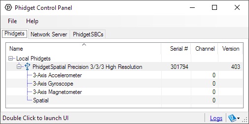
First Look
After plugging the 1044 into your computer and opening the Phidget Control Panel, you will see something like this:
The Phidget Control Panel will list all connected Phidgets and associated objects, as well as the following information:
- Serial number: allows you to differentiate between similar Phidgets.
- Channel: allows you to differentiate between similar objects on a Phidget.
- Version number: corresponds to the firmware version your Phidget is running. If your Phidget is listed in red, your firmware is out of date. Update the firmware by double-clicking the entry.
The Phidget Control Panel can also be used to test your device. Double-clicking on an object will open an example.
Accelerometer
Double-click on the Accelerometer object {{{2}}} in order to run the example:
[[Image:{{{1}}}_Accelerometer_Example.jpg|center|link=]]
General information about the selected object will be displayed at the top of the window. You can also experiment with the following functionality:
- Modify the change trigger and/or data interval value by dragging the sliders. For more information on these settings, see the data interval/change trigger page.
- The measured values reported in g-force can be seen via labels as well as graphical dials. Try tilting the {{{1}}} in different directions to see the labels and graphics change.
- An extremely accurate timestamp is also reported with the g-force values.
Gyroscope
Double-click on the Gyroscope object in order to run the example:
[[Image:{{{1}}}_Gyroscope_Example.jpg|center|link=]]
General information about the selected object will be displayed at the top of the window. You can also experiment with the following functionality:
- Modify the change trigger and/or data interval value by dragging the sliders. For more information on these settings, see the data interval/change trigger page.
- The Zero Gyro button is used to compensate for the drift that is inherent to all gyroscopes. The gyroscope primer has more information about this subject.
- The measured values reported in degrees per second can be seen via labels as well as graphical dials. Try rotating the {{{1}}} in different directions to see the labels and graphics change.
- An extremely accurate timestamp is also reported with the g-force values.
Magnetometer
Double-click on the Magnetometer object in order to run the example:
[[Image:{{{1}}}_Magnetometer_Example.jpg|center|link=]]
General information about the selected object will be displayed at the top of the window. You can also experiment with the following functionality:
- Modify the change trigger and/or data interval value by dragging the sliders. For more information on these settings, see the data interval/change trigger page.
- Use the Set Params... button to set the calibration parameters. For more information about calibration, see the technical section.
- The measured values reported in Gauss can be seen via labels as well as a graphical diagram. The diagram can help you visualize the magnetic field vector.
- An extremely accurate timestamp is also reported with the Gauss values.
Spatial
Double-click on the Spatial object in order to run the example:
[[Image:{{{1}}}_Spatial_Example.jpg|center|link=]]
The Spatial example demonstrates that you can receive data from the accelerometer, gyroscope, and magnetometer all at once by using the Spatial object rather than the other three objects individually.
Testing Using macOS
- Go to the Quick Downloads section on the macOS page.
- Download and run the Phidget macOS Installer
- Click on System Preferences >> Phidgets (under Other) to activate the Preference Pane
- Make sure your device is properly attached
- Double click on your device's objects in the listing to open them. The Preference Pane and examples will function very similarly to the ones described above in the Windows section.
Testing Using Linux
For a general step-by-step guide on getting Phidgets running on Linux, see the Linux page.
Using a Remote OS
We recommend testing your Phidget on a desktop OS before moving on to remote OS. Once you've tested your Phidget, you can go to the PhidgetSBC, or iOS pages to learn how to proceed.
Technical Details
High Resolution Mode
When the PhidgetSpatial High Resolution 3/3/3 measures an acceleration value with magnitude less than 2g, it will acquire its data from a higher precision accelerometer chip. For these measurements, the average white noise on each axis will be reduced by approximately a factor of ten, and the resolution will increase from 976 μg to 76 μg. Likewise, when the gyroscope measures a rotation value with magnitude less than 300 °/s on the Z-axis or 400 °/s on the X or Y-axis, the noise per axis will be approximately six times lower, and the resolution will increase from 0.07 °/s to 0.02 °/s.
The transition from normal to high precision or vice-versa is seamless, with no additional code or equations needed.
3-Axis Accelerometer
The PhidgetSpatial 3/3/3 has a 3-Axis accelerometer that can measure ±8 g (±78 m/s2) per axis. It will measure both dynamic acceleration (change in velocity) and static acceleration (gravity vector).
For more information on how to use the accelerometer, check the Accelerometer Primer.
3-Axis Gyroscope
For more information on the gyroscope, see the Gyroscope Primer.
3-Axis Magnetometer (Compass)
The magnetometer reports the sum of all magnetic fields acting on the 1044 device. The earth’s magnetic field is only one source that affects this measurement. In order to get accurate bearing data from the magnetometer - ie. to find magnetic north as a compass - any interfering magnetic effects need to be calibrated out. For more information about calibration, see the section below, or the Compass Primer.
Any magnetic field that is stationary with respect to the 1044 device, and less than ± 3 Gauss, can be calibrated out of the magnetic field measurement. This includes both hard and soft iron effects caused by nearby ferrous and magnetic materials. Interfering magnetic fields that vary in strength and orientation with respect to the 1044 device cannot be easily calibrated out.
Magnetic field data will become unavailable during every other sample as the compass performs internal calibrations. When this happens, the magneticField array in the SpatialData structure will either have a length of zero, or each element will equal PUNK_DBL, depending on the API being used. This needs to be handled explicitly in the event handling code to avoid erroneous program behavior. The maximum sampling rate of the compass is 125 Hz.
Template:Compasscalibration
For more information on magnetometers (compasses), see the Compass Primer.
What to do Next
- Programming Languages - Find your preferred programming language here and learn how to write your own code with Phidgets!
- Phidget Programming Basics - Once you have set up Phidgets to work with your programming environment, we recommend you read our page on to learn the fundamentals of programming with Phidgets.
Product History
Template:UGhist
Template:UGrow
Template:UGrow
Template:UGrow