|
|
| (15 intermediate revisions by 2 users not shown) |
| Line 1: |
Line 1: |
| | __NOINDEX__ |
| | __NOTOC__ |
| | <metadesc>Add 4 digital inputs to your VINT Hub with the 4x Digital Input Phidget. These inputs react faster than a VINT port in Digital Input mode.</metadesc> |
| [[Category:UserGuide]] | | [[Category:UserGuide]] |
| ==Getting Started== | | == Part 1: Setup == |
| {{UGIntro|DAQ1200}} | | {{PT1 Deck Sequence}} |
| *[{{SERVER}}/products.php?product_id=DAQ1200 DAQ1200 - 4x Digital Input Phidget]
| |
| * {{VINTHub}}
| |
| * [{{SERVER}}/?view=comparetable&rel=Phidget%20Cables Phidget cable]
| |
| * USB cable and computer
| |
| * something to use with the DAQ1200 (e.g. switch or digital sensor with a digital output)
| |
|
| |
|
| | == Part 2: Using Your Phidget == |
|
| |
|
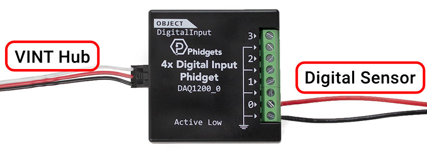
| Next, you will need to connect the pieces:
| | ===About=== |
| [[Image:DAQ1200_Functional.jpeg|600px|right|link=]]
| | Read four digital output devices with the DAQ1200. This Phidget is best suited for reading switches, or 5V logic level devices. |
| # Connect the DAQ1200 to the VINT Hub using the Phidget cable.
| |
| # Connect the VINT Hub to your computer with a USB cable.
| |
| # Connect a switch or digital sensor to one of the DAQ1200's inputs.
| |
|
| |
|
| <br clear="all">
| | [[Image:DAQ1200_About.jpg|link=|center]] |
| {{UGIntroDone|DAQ1200}}.
| |
|
| |
|
| ==Using the DAQ1200==
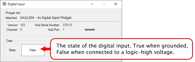
| | The DAQ1200 is an active-low device. You interact with the DAQ1200 through the Digital Input Channel Class. The Digital Input state equals ''true'' when grounded and ''false'' when connected to a high voltage. |
| {{UGcontrolpanel|DAQ1200}}
| |
|
| |
|
| {{ugDigitalInput|DAQ1200|{{UGDigitalInputActiveLow}}}}
| | ===Explore Your Phidget Channels Using The Control Panel=== |
|
| |
|
| | You can use your Control Panel to explore your Phidget's channels. |
|
| |
|
| ==Technical Details==
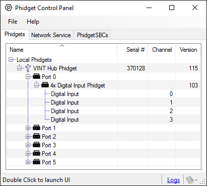
| | '''1.''' Open your Control Panel, and you will find the following channels: |
| ===General===
| |
| The DAQ1200 features four digital input terminals, all of which share a common ground. Each input has a built-in pull-up resistor to allow for easy interfacing to all manner of switches.
| |
|
| |
|
| ===Example Use=== | | [[Image:DAQ1200_Panel.jpg|link=|center]] |
| Here are a few things you can do with the DAQ1200 Digital Output Phidget
| |
|
| |
|
| ====Use with a Switch==== | | '''2.''' Double click on a channel to open an example program. Each channel belongs to the '''Digital Input''' channel class: |
| | |
| | {{UGC-Start}} |
| | |
| | {{UGC-Entry|Digital Input:| Read the state of a 5V digital signal| |
| | In your Control Panel, double click on "Digital Input": |
| | |
| | [[Image:DAQ1200-test-DigitalInput.jpg|center|link=]]}} |
| | |
| | For more information about Digital Inputs, take a look at the [[Digital Input Guide]]. |
| | |
| | {{UGC-End}} |
| | |
| | {{UG-Part3}} |
| | |
| | == Part 4: Advanced Topics and Troubleshooting == |
| | |
| | {{UGC-Start}} |
| | {{UGC-Addressing}} |
| | {{UGC-Graphing}} |
| | {{UGC-Firmware}} |
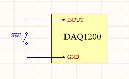
| | {{UGC-Entry|Using the DAQ1200 with a Switch|| |
| [[Image:DAQ1200_SwitchInput.jpg|link=|350px|right]] | | [[Image:DAQ1200_SwitchInput.jpg|link=|350px|right]] |
| To interface a switch with the DAQ1200, simply connect the switch across the input and ground terminals for a channel. | | To interface a switch with the DAQ1200, simply connect the switch across the input and ground terminals for a channel. |
| <br clear="all">
| | }} |
| | | {{UGC-Entry|Using the DAQ1200 with 5V Logic Level Devices|| |
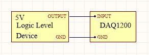
| ====Use with 5V Logic Level Devices====
| |
| [[Image:DAQ1200_LogicInput.jpg|link=|350px|right]] | | [[Image:DAQ1200_LogicInput.jpg|link=|350px|right]] |
| The DAQ1200 can also detect signals from 5V logic level devices. Be aware that the input is active-low, which means that LOW voltages will be detected as TRUE, and HIGH voltages as FALSE. | | The DAQ1200 can also detect signals from 5V logic level devices. Be aware that the input is active-low, which means that LOW voltages will be detected as TRUE, and HIGH voltages as FALSE. |
| <br clear="all">
| | }} |
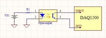
| | {{UGC-Entry|Isolation with Optocouplers|| |
| | [[Image:DAQ1200_Optocoupler_Diagram.jpg|link=|350px|right]] |
| | |
| | In some applications, particularly where there is a lot of electrical noise (automotive), or where you want maximum protection of the circuitry (interactive installations, kiosks), electrical isolation buys you a huge margin of protection. |
| | |
| | If wired according to the diagram, driving the LED will cause the DAQ1200 to report TRUE. |
|
| |
|
| {{UGnext|}} | | Note that in cases where many isolated inputs are required, or for simplicity's sake, you may want to consider using the {{Prod|DAQ1300}} or {{Prod|DAQ1301}}, which are (more sophisticated) ready-made isolated digital input Phidgets. |
| | }} |
| | {{UGC-End}} |
Part 1: Setup
Your Phidget must be connected to a device with a VINT port using a 3-wire Phidget cable.
Which device are you connecting to?
HUB0000 - HUB0007
USB VINT Hubs
Select your Operating System:
Select your Operating System:
Select your Operating System:
Step 1: Install Phidgets Library
Step 2: Connect Devices
Step 3: Verify Connection
Step 1: Install Phidgets Library
Before you begin using your Phidgets, you will need to install the Phidget Library.
1. Download the installer for your system:
● 32-bit Installer Download
● 64-bit Installer Download
If you're unsure which one you should get, press ⊞ WIN + Pause/Break:
Before installing our libraries, be sure to read our Software License.
Step 1: Install Phidgets Library
2. Open the download. If it asks you for permission, select Run
Step 1: Install Phidgets Library
3a. Select Next
Step 1: Install Phidgets Library
3b. Read the Licence Agreement. Select Next.
Step 1: Install Phidgets Library
3c. Choose Installation Location. Select Next.
Step 1: Install Phidgets Library
3d. Confirm Install
Step 1: Install Phidgets Library
3e. Wait for Installation to complete. This should only take a few moments.
Step 1: Install Phidgets Library
3f. Installation Complete. Close installation Window.
Step 2: Connect Devices
● Connect USB Cable to your Windows Computer
● Connect VINT Device(s)
Step 3: Verify Connection
1. Open the Phidgets Control Panel:
If your Control Panel does not open, look in your taskbar. Double click the Phidget Icon.
Step 3: Verify Connection
2. If connected, your Phidgets will appear in the Phidget Control Panel.
Done!
If you're able to see and interact with your devices in the Phidget Control Panel, you're done with the Setup part of this guide.
Scroll down to Part 2: Using Your Phidget for the next step.
For more help installing in Windows (e.g. manual install, using a VM, etc.), visit this page:
● Windows Advanced Information
Step 1: Install Phidgets Library
Step 2: Connect Devices
Step 3: Verify Connection
Step 1: Install Phidgets Library
Before you begin using your Phidgets, you will need to install the Phidget Library.
1. Download the installer for your system:
● macOS 10.11+: Installer Download
● macOS 10.7 - macOS 10.10: Installer Download
● macOS 10.5 - macOS 10.6: Installer Download
Before installing our libraries, be sure to read our Software License.
Step 1: Install Phidgets Library
2. Open the download and double click on Phidgets.pkg
Step 1: Install Phidgets Library
3a. Select Continue
Step 1: Install Phidgets Library
3b. Read and continue. Read the License and click Agree.
Step 1: Install Phidgets Library
3c. Here, you have the option to select the installation location. Select Install to continue.
Step 1: Install Phidgets Library
3d. MacOS may ask for permission to install. Enter your username and password and Install Software.
Step 1: Install Phidgets Library
3e. Wait for Installation to complete. This should only take a few moments.
Step 1: Install Phidgets Library
3f. You may see a message that the extension has been blocked. Select Open Security Preferences.
Step 1: Install Phidgets Library
3g. Beside the message for Phidgets Inc, Click Allow.
Step 1: Install Phidgets Library
3h. Installation Complete, Click Close.
Step 1: Install Phidgets Library
3i. To delete the installer, click Move to Trash.
Step 2: Connect Devices
● Connect USB Cable to your Mac
● Connect VINT Device(s)
Step 3: Verify Connection
1. Open the Phidgets Control Panel:
Step 3: Verify Connection
2. If connected, your Phidgets will appear in the Phidget Control Panel.
Done!
If you're able to see and interact with your devices in the Phidget Control Panel, you're done with the Setup part of this guide.
Scroll down to Part 2: Using Your Phidget for the next step.
For more info installing in MacOS (e.g. developer tools, driver extension, etc.), visit this page:
● MacOS Advanced Information
Step 1: Install Phidgets Library
Step 2: Connect Devices
Step 3: Verify Connection
Step 1: Install Phidgets Library
1. First, you need to install the libusb-1.0 development libraries. For example, in Debian based distributions:
apt-get install libusb-1.0-0-dev
You’ll also need a C compiler and builder, if you don’t already have one installed.
apt-get install gcc
apt-get install make
Step 1: Install Phidgets Library
2. Next, download and unpack the Phidgets library:
● libphidget22
Step 1: Install Phidgets Library
3. Use the following commands in the location you unpacked to install the library:
./configure
make
sudo make install
Step 1: Install Phidgets Library
4. (Optional) You can also download and unpack the following optional packages:
● phidget22networkserver - Phidget Network Server, which
enables the use of Phidgets over your network
● phidget22admin - Admin tool to track who is connected to your
Phidgets when using the network server
● libphidget22extra - Required for phidget22networkserver
and phidget22admin
● libphidget22java - The Java libraries for Phidget22
For installation instructions for these packages, see the README file included with each one.
Step 2: Connect Devices
● Connect USB Cable to your Linux Computer
● Connect VINT Device(s)
Step 3: Verify Connection
1. The easiest way to verify that your libraries are working properly is to compile and run an example program. Download and unpack this C example that will
detect any Phidget:
● HelloWorld C Example
Step 3: Verify Connection
2. Next, open the terminal in the location where you unpacked the example. Compile and run using:
gcc HelloWorld.c -o HelloWorld -lphidget22
sudo ./HelloWorld
ou should receive a “Hello” line for each Phidget channel that is discovered:
You need to run it with sudo in order to be able to access USB devices. In order to use
Phidgets without sudo, you need to set your udev rules. See the Advanced Information page on the final slide of this guide for details.
Done!
If you're able to see your devices in the Hello World example, you're done with the Setup part of this guide.
Scroll down to Part 2: Using Your Phidget for the next step.
For more info installing in Linux (e.g. Udev rules, old versions, etc.), visit this page:
● Linux Advanced Information
Step 1: Install Phidgets Library
Step 2: Connect Devices
Step 3: Connect Wireless
Step 4: Verify Connection
Step 5: Update
Step 1: Install Phidgets Library
Before you begin using your Phidgets, you will need to install the Phidget Library.
1. Download the installer for your system:
● 32-bit Installer Download
● 64-bit Installer Download
If you're unsure which one you should get, press ⊞ WIN + Pause/Break:
Before installing our libraries, be sure to read our Software License.
Step 1: Install Phidgets Library
2. Open the download. If it asks you for permission, select Run
Step 1: Install Phidgets Library
3a. Select Next
Step 1: Install Phidgets Library
3b. Read the Licence Agreement. Select Next.
Step 1: Install Phidgets Library
3c. Choose Installation Location. Select Next.
Step 1: Install Phidgets Library
3d. Select Next to confirm install.
Step 1: Install Phidgets Library
3e. Wait for Installation to complete. This should only take a few moments.
Step 1: Install Phidgets Library
3f. Installation Complete. Close installation Window.
Step 2: Connect Devices
● Connect Power Jack
● Connect VINT Device(s)
● Connect Ethernet to a Router or Switch (optional)
Step 3: Verify Connection
Choose a setup method:
Configure with mobile device
Connect with ethernet cable
(Requires physical access to router or switch)
Step 3: Connect Wireless
1. When you connect the power supply to the HUB5000, the red LED should turn on.
Step 3: Connect Wireless
2. On your mobile device, go to the Wi-Fi settings and connect to the HUB5000:
Step 3: Connect Wireless
3. When asked for a password, enter the password printed on the HUB5000’s label.
Step 3: Connect Wireless
4. Once your device is connected to the HUB5000’s WiFi signal:
Click on the WiFi network and find an option that says “Manage router” or “Visit homepage”.
Go to your internet browser and type 192.168.100.1 in the address bar.
Step 3: Connect Wireless
5. Create a password for your HUB5000. You'll use it to access the Configure Page from now on.
Step 3: Connect Wireless
6. Navigate to the network page. Change the Mode to Client.
Step 3: Connect Wireless
7. Enter your Wifi Network details and click Save & Apply. It may take a few minutes for your Phidgets to appear in the Phidget Control Panel, which
we’ll check in the next step.
Step 4: Verify Connection
1. Open the Phidgets Control Panel:
If your Control Panel does not open, look in your taskbar. Double click the Phidget Icon.
Step 4: Verify Connection
2. If connected, your Phidgets will appear in the Phidget Control Panel.
Step 5: Update
Now that you've confirmed that you have access to your Phidgets, you should ensure the HUB5000 is fully updated. You can update the firmware of the VINT Hub by
going back to the Phidget Control Panel. If there's a blue arrow beside the version number, it means an update is available:
Right-click anywhere on that row and select Upgrade Firmware. When it's done, the number in the Version column will change.
Step 5: Update
Next, to update the OS firmware, go to the Network Phidgets tab in the control panel, find your HUB5000 and double-click on it. If the OS firmware is out
of date, you'll see the following window pop up with steps to follow:
1. Download the firmware (you can get it here if the button does not
work)
2. Open the web interface by clicking the button or entering the HUB5000's IP address in your web browser.
3. Go to the System tab and scroll down to the Upgrade Firmware section. Select the file you just downloaded and click Upgrade and Restart.
You'll be instructed to wait a few minutes before logging back into the web interface.
Step 5: Update
When you log back in, you can confirm that the new version has successfully installed by checking to see if the firmware version listed in the
Status section matches the first three numbers in the firmware file name that you downloaded. You can also check the version in the
Network Phidgets tab on the Phidget Control Panel.
Done!
Now that you're able to see and interact with your devices in the Phidget Control Panel and they're fully updated, you're done with the Setup part of this
guide.
Scroll down to Part 2: Using Your Phidget for the next step.
For more help installing in Windows (e.g. manual install, using a VM, etc.), visit this page:
● Windows Advanced Information
Step 3: Connect Wireless
1. When you connect the power supply to the HUB5000, the red LED should turn on.
Step 3: Connect Wireless
2. In your Web Browser, enter hub5000.local
Step 3: Connect Wireless
3. Create a password for your HUB5000. You'll use this password to access the Configure Page from now on.
Step 3: Connect Wireless
4. Navigate to the network page. Change the Mode to Client.
Step 3: Connect Wireless
5. Enter your Wifi Network details to use your Hub wirelessly and click Save & Apply. You can then disconnect the ethernet cable.
It may take a few minutes for your Phidgets to appear in the Phidget Control Panel, which we’ll check in the next step.
Step 4: Verify Connection
1. Open the Phidgets Control Panel:
If your Control Panel does not open, look in your taskbar. Double click the Phidget Icon.
Step 4: Verify Connection
2. If connected, your Phidgets will appear in the Phidget Control Panel.
Step 5: Update
Now that you've confirmed that you have access to your Phidgets, you should ensure the HUB5000 is fully updated. You can update the firmware of the VINT Hub by
going back to the Phidget Control Panel. If there's a blue arrow beside the version number, it means an update is available:
Right-click anywhere on that row and select Upgrade Firmware. When it's done, the number in the Version column will change.
Step 5: Update
Next, to update the OS firmware, go to the Network Phidgets tab in the control panel, find your HUB5000 and double-click on it. If the OS firmware is out
of date, you'll see the following window pop up with steps to follow:
1. Download the firmware (you can get it here if the button does not
work)
2. Open the web interface by clicking the button or entering the HUB5000's IP address in your web browser.
3. Go to the System tab and scroll down to the Upgrade Firmware section. Select the file you just downloaded and click Upgrade and Restart.
You'll be instructed to wait a few minutes before logging back into the web interface.
Step 5: Update
When you log back in, you can confirm that the new version has successfully installed by checking to see if the firmware version listed in the
Status section matches the first three numbers in the firmware file name that you downloaded. You can also check the version in the
Network Phidgets tab on the Phidget Control Panel.
Done!
Now that you're able to see and interact with your devices in the Phidget Control Panel and they're fully updated, you're done with the Setup part of this
guide.
Scroll down to Part 2: Using Your Phidget for the next step.
For more help installing in Windows (e.g. manual install, using a VM, etc.), visit this page:
● Windows Advanced Information
Step 1: Install Phidgets Library
Step 2: Connect Devices
Step 3: Connect Wireless
Step 4: Verify Connection
Step 5: Update
Step 1: Install Phidgets Library
Before you begin using your Phidgets, you will need to install the Phidget Library.
1. Download the installer for your system:
● macOS 10.11+: Installer Download
● macOS 10.7 - macOS 10.10: Installer Download
● macOS 10.5 - macOS 10.6: Installer Download
Before installing our libraries, be sure to read our Software License.
Step 1: Install Phidgets Library
2. Open the download and double click on Phidgets.pkg
Step 1: Install Phidgets Library
3a. Select Continue
Step 1: Install Phidgets Library
3b. Read and continue. Read the License and click Agree.
Step 1: Install Phidgets Library
3c. Here, you have the option to select the installation location. Select Install.
Step 1: Install Phidgets Library
3d. MacOS may ask for permission to install. Enter your username and password and Install Software.
Step 1: Install Phidgets Library
3e. Wait for Installation to complete. This should only take a few moments.
Step 1: Install Phidgets Library
3f. You may see a message that the extension has been blocked. Select Open Security Preferences.
Step 1: Install Phidgets Library
3g. Beside the message for Phidgets Inc, Click Allow.
Step 1: Install Phidgets Library
3h. Installation Complete, Click Close.
Step 1: Install Phidgets Library
3i. To delete the installer, click Move to Trash.
Step 2: Connect Devices
● Connect Power Jack
● Connect VINT Device(s)
● Connect Ethernet to a Router or Switch (optional)
Step 3: Verify Connection
Choose a setup method:
Configure with mobile device
Connect with ethernet cable
(Requires physical access to router or switch)
Step 3: Connect Wireless
1. When you connect the power supply to the HUB5000, the red LED should turn on.
Step 3: Connect Wireless
2. On your mobile device, go to the Wi-Fi settings and connect to the HUB5000:
Step 3: Connect Wireless
3. When asked for a password, enter the password printed on the HUB5000’s label.
Step 3: Connect Wireless
4. Once your device is connected to the HUB5000’s WiFi signal:
Click on the WiFi network and find an option that says “Manage router” or “Visit homepage”.
Go to your internet browser and type 192.168.100.1 in the address bar.
Step 3: Connect Wireless
5. Create a password for your HUB5000. You'll use this password to access the Configure Page from now on.
Step 3: Connect Wireless
6. Navigate to the network page. Change the Mode to Client.
Step 3: Connect Wireless
7. Enter your Wifi Network details and click Save & Apply. It may take a few minutes for your Phidgets to appear in the Phidget Control Panel, which
we’ll check in the next step.
Step 4: Verify Connection
1. Open the Phidget Control Panel:
Step 4: Verify Connection
2. If connected, your Phidgets will appear in the Phidget Control Panel.
Step 5: Update
Now that you've confirmed that you have access to your Phidgets, you should ensure the HUB5000 is fully updated. You can update the firmware of the VINT Hub by
going back to the Phidget Control Panel. If the name of the device is red, it means an update is available:
Double click on the device in the control panel to update the VINT Hub firmware. When it's finished, the text will turn from red to black and the number in the
Version column will change.
Step 5: Update
To upgrade the firmware of the operating system on the HUB5000, download the most recent file
here.
Next, go back to the web configuration page and click on the System tab. Scroll down to Upgrade Firmware and select the file you download and hit
Upgrade & Restart. You'll be instructed to wait a few minutes before logging back into the web interface.
When you log back in, you can confirm that the new version has successfully installed by checking to see if the firmware version listed in the
Status section matches the first three numbers in the firmware file name that you downloaded.
Done!
Now that you're able to see and interact with your devices in the Phidget Control Panel, you're done with the Setup part of this guide.
Scroll down to Part 2: Using Your Phidget for the next step.
For more info installing in MacOS (e.g. developer tools, driver extension, etc.), visit this page:
● MacOS Advanced Information
Step 3: Connect Wireless
1. When you connect the power supply to the HUB5000, the red LED should turn on.
Step 3: Connect Wireless
2. In your Web Browser, enter hub5000.local
Step 3: Connect Wireless
3. Create a password for your HUB5000. You'll use this password to access the Configure Page from now on.
Step 3: Connect Wireless
4. Navigate to the network page. Change the Mode to Client.
Step 3: Connect Wireless
5. Enter your Wifi Network details to use your Hub wirelessly and click Save & Apply. You can then disconnect the ethernet cable.
It may take a few minutes for your Phidgets to appear in the Phidget Control Panel, which we’ll check in the next step.
Step 4: Verify Connection
1. Open the Phidget Control Panel:
Step 4: Verify Connection
2. If connected, your Phidgets will appear in the Phidget Control Panel.
Step 5: Update
Now that you've confirmed that you have access to your Phidgets, you should ensure the HUB5000 is fully updated. You can update the firmware of the VINT Hub by
going back to the Phidget Control Panel. If the name of the device is red, it means an update is available:
Double click on the device in the control panel to update the VINT Hub firmware. When it's finished, the text will turn from red to black and the number in the
Version column will change.
Step 5: Update
To upgrade the firmware of the operating system on the HUB5000, download the most recent file
here.
Next, go back to the web configuration page and click on the System tab. Scroll down to Upgrade Firmware and select the file you download and hit
Upgrade & Restart. You'll be instructed to wait a few minutes before logging back into the web interface.
When you log back in, you can confirm that the new version has successfully installed by checking to see if the firmware version listed in the
Status section matches the first three numbers in the firmware file name that you downloaded.
Done!
Now that you're able to see and interact with your devices in the Phidget Control Panel, you're done with the Setup part of this guide.
Scroll down to Part 2: Using Your Phidget for the next step.
For more info installing in MacOS (e.g. developer tools, driver extension, etc.), visit this page:
● MacOS Advanced Information
Step 1: Install Phidgets Library
Step 2: Connect Devices
Step 3: Connect Wireless
Step 4: Verify Connection
Step 5: Update
Step 1: Install Phidgets Library
1. First, you need to install the libusb-1.0 development libraries. For example, in Debian based distributions:
apt-get install libusb-1.0-0-dev
You’ll also need a C compiler and builder, if you don’t already have one installed.
apt-get install gcc
apt-get install make
Step 1: Install Phidgets Library
2. Next, download and unpack the Phidgets library:
● libphidget22
Step 1: Install Phidgets Library
3. Use the following commands in the location you unpacked to install the library:
./configure
make
sudo make install
Step 1: Install Phidgets Library
4. (Optional) You can also download and unpack the following optional packages:
● phidget22networkserver - Phidget Network Server, which
enables the use of Phidgets over your network
● phidget22admin - Admin tool to track who is connected to your
Phidgets when using the network server
● libphidget22extra - Required for phidget22networkserver
and phidget22admin
● libphidget22java - The Java libraries for Phidget22
For installation instructions for these packages, see the README file included with each one.
Step 2: Connect Devices
● Connect Power Jack
● Connect VINT Device(s)
● Connect Ethernet to a Router or Switch (optional)
Step 3: Verify Connection
Choose a setup method:
Configure with mobile device
Connect with ethernet cable
(Requires physical access to router or switch)
Step 3: Connect Wireless
1. When you connect the power supply to the HUB5000, the red LED should turn on.
Step 3: Connect Wireless
2. On your mobile device, go to the Wi-Fi settings and connect to the HUB5000:
Step 3: Connect Wireless
3. When asked for a password, enter the password printed on the HUB5000’s label.
Step 3: Connect Wireless
4. Once your device is connected to the HUB5000’s WiFi signal:
Click on the WiFi network and find an option that says “Manage router” or “Visit homepage”.
Go to your internet browser and type 192.168.100.1 in the address bar.
Step 3: Connect Wireless
5. Create a password for your HUB5000. You'll use this password to access the Configure Page from now on.
Step 3: Connect Wireless
6. Navigate to the network page. Change the Mode to Client.
Step 3: Connect Wireless
7. Enter your Wifi Network details and click Save & Apply. It may take a few minutes for your Phidgets to appear in the Phidget Control Panel, which
we’ll check in the next step.
Step 4: Verify Connection
1. The easiest way to verify that your libraries are working properly is to compile and run an example program. Download and unpack this C example that will
detect any Phidget:
● HelloWorld C Example
Step 4: Verify Connection
2. Next, open the terminal in the location where you unpacked the example. Compile and run using:
gcc HelloWorld.c -o HelloWorld -lphidget22
sudo ./HelloWorld
ou should receive a “Hello” line for each Phidget channel that is discovered:
You need to run it with sudo in order to be able to access USB devices. In order to use
Phidgets without sudo, you need to set your udev rules. See the Advanced Information page on the final slide of this guide for details.
Step 5: Update
Now that you've confirmed that you have access to your Phidgets, you should ensure the HUB5000 is fully updated. You can update the firmware of the VINT Hub
using the phidget22admin tool (see included readme for further
instructions).
To upgrade the firmware of the operating system on the HUB5000, download the most recent file
here.
Next, go back to the web configuration page and click on the System tab. Scroll down to Upgrade Firmware and select the file you download and hit
Upgrade & Restart. You'll be instructed to wait a few minutes before logging back into the web interface.
When you log back in, you can confirm that the new version has successfully installed by checking to see if the firmware version listed in the
Status section matches the first three numbers in the firmware file name that you downloaded.
Done!
Now that you're able to see your devices in the Hello World example and the device is fully updated, you're done with the Setup part of this guide.
Scroll down to Part 2: Using Your Phidget for the next step.
For more info installing in Linux (e.g. Udev rules, old versions, etc.), visit this page:
● Linux Advanced Information
Step 3: Connect Wireless
1. When you connect the power supply to the HUB5000, the red LED should turn on.
Step 3: Connect Wireless
2. In your Web Browser, enter hub5000.local
Step 3: Connect Wireless
3. Create a password for your HUB5000. You'll use this password to access the Configure Page from now on.
Step 3: Connect Wireless
4. Navigate to the network page. Change the Mode to Client.
Step 3: Connect Wireless
5. Enter your Wifi Network details to use your Hub wirelessly and click Save & Apply. You can then disconnect the ethernet cable.
It may take a few minutes for your Phidgets to appear in the Phidget Control Panel, which we’ll check in the next step.
Step 4: Verify Connection
1. The easiest way to verify that your libraries are working properly is to compile and run an example program. Download and unpack this C example that will
detect any Phidget:
● HelloWorld C Example
Step 4: Verify Connection
2. Next, open the terminal in the location where you unpacked the example. Compile and run using:
gcc HelloWorld.c -o HelloWorld -lphidget22
sudo ./HelloWorld
You should receive a “Hello” line for each Phidget channel that is discovered:
You need to run it with sudo in order to be able to access USB devices. In order to use
Phidgets without sudo, you need to set your udev rules. See the Advanced Information page on the final slide of this guide for details.
Step 5: Update
Now that you've confirmed that you have access to your Phidgets, you should ensure the HUB5000 is fully updated. You can update the firmware of the VINT Hub
using the phidget22admin tool (see included readme for further
instructions).
To upgrade the firmware of the operating system on the HUB5000, download the most recent file
here.
Next, go back to the web configuration page and click on the System tab. Scroll down to Upgrade Firmware and select the file you download and hit
Upgrade & Restart. You'll be instructed to wait a few minutes before logging back into the web interface.
When you log back in, you can confirm that the new version has successfully installed by checking to see if the firmware version listed in the
Status section matches the first three numbers in the firmware file name that you downloaded.
Done!
Now that you're able to see your devices in the Hello World example and the device is fully updated, you're done with the Setup part of this guide.
Scroll down to Part 2: Using Your Phidget for the next step.
For more info installing in Linux (e.g. Udev rules, old versions, etc.), visit this page:
● Linux Advanced Information
Step 1: Install Phidgets Library
Step 2: Connect Devices
Step 3: Verify Connection
Step 4: Connect Wireless
Step 1: Install Phidgets Library
Before you begin using your Phidgets, you will need to install the Phidget Library.
1. Download the installer for your system:
● 32-bit Installer Download
● 64-bit Installer Download
If you're unsure which one you should get, press ⊞ WIN + Pause/Break:
Before installing our libraries, be sure to read our Software License.
Step 1: Install Phidgets Library
2. Open the download. If it asks you for permission, select Run.
Step 1: Install Phidgets Library
3a. Select Next.
Step 1: Install Phidgets Library
3b. Read the Licence Agreement. Select Next.
Step 1: Install Phidgets Library
3c. Choose Installation Location. Select Next.
Step 1: Install Phidgets Library
3d. Select Next.
Step 1: Install Phidgets Library
3e. Wait for Installation to complete. This should only take a few moments.
Step 1: Install Phidgets Library
3f. Installation Complete. Close installation Window.
Step 2: Connect Devices
● Connect Power Jack
● Connect VINT Device(s)
● Connect Ethernet to a Router or Switch in the same network as your Windows PC
Step 3: Verify Connection
1. Open the Phidgets Control Panel:
If your Control Panel does not open, look in your taskbar. Double click the Phidget Icon.
Step 3: Verify Connection
2. If connected, your Phidgets will appear in the Phidget Control Panel.
Now that the SBC's ethernet connection is verified, it can be connected to wifi.
If you don't have a USB wifi adapter or you're planning to stay on ethernet, you can scroll down to
Part 2: Using Your Phidget
Step 4: Connect Wireless
1. In your web browser, enter phidgetsbc.local
Step 4: Connect Wireless
2. Create a password for your SBC. You'll use this to access the configuration page from now on.
Step 4: Connect Wireless
3. Navigate to Network -> Wireless. Select your Network, enter the wifi password and select Add This Network.
Step 4: Connect Wireless
4. Scroll down to your saved networks, click on your network and select Join This Network.
Step 4: Connect Wireless
5. It should now say connected in the status column.
You can now unplug the ethernet cable.
Step 4: Connect Wireless
6. Return to the Phidget Control Panel to access your Phidgets.
Done!
If you're able to see and interact with your devices in the Phidget Control Panel, you're done with the Setup part of this guide.
Scroll down to Part 2: Using Your Phidget for the next step.
For more help installing in Windows (e.g. manual install, using a VM, etc.), visit this page:
● Windows Advanced Information
Step 1: Install Phidgets Library
Step 2: Connect Devices
Step 3: Verify Connection
Step 4: Connect Wireless
Step 1: Install Phidgets Library
Before you begin using your Phidgets, you will need to install the Phidget Library.
1. Download the installer for your system:
● macOS 10.11+: Installer Download
● macOS 10.7 - macOS 10.10: Installer Download
● macOS 10.5 - macOS 10.6: Installer Download
Before installing our libraries, be sure to read our Software License.
Step 1: Install Phidgets Library
2. Open the download and double click on Phidgets.pkg
Step 1: Install Phidgets Library
3a. Select Continue
Step 1: Install Phidgets Library
3b. Read and continue. Read the License and click Agree.
Step 1: Install Phidgets Library
3c. Here, you have the option to select the installation location. Select Install.
Step 1: Install Phidgets Library
3d. MacOS may ask for permission to install. Enter your username and password and Install Software.
Step 1: Install Phidgets Library
3e. Wait for Installation to complete. This should only take a few moments.
Step 1: Install Phidgets Library
3f. You may see a message that the extension has been blocked. Select Open Security Preferences.
Step 1: Install Phidgets Library
3g. Click Allow.
Step 1: Install Phidgets Library
3h. Installation Complete, Click Close.
Step 1: Install Phidgets Library
3i. To delete the installer, click Move to Trash.
Step 2: Connect Devices
● Connect Power Jack
● Connect VINT Device(s)
● Connect Ethernet to a Router or Switch in the same network as your Mac
Step 3: Verify Connection
1. Open the Phidget Control Panel:
Step 3: Verify Connection
2. If connected, your Phidgets will appear in the Phidget Control Panel.
Now that the SBC's ethernet connection is verified, it can be connected to wifi.
If you don't have a USB wifi adapter or you're planning to stay on ethernet, you can scroll down to
Part 2: Using Your Phidget
Step 4: Connect Wireless
1. In your web browser, enter phidgetsbc.local
Step 4: Connect Wireless
2. Create a password for your SBC. You will use this to access the configuration page from now on.
Step 4: Connect Wireless
3. Navigate to Network -> Wireless. Select your Network, enter the wifi password and select Add This Network.
Step 4: Connect Wireless
4. Scroll down to your saved networks, click on your network and select Join This Network.
Step 4: Connect Wireless
5. It should now say connected in the status column.
You can now unplug the ethernet cable.
Step 4: Connect Wireless
6. Return to the Phidget Control Panel to access your Phidgets.
Done!
If you're able to see and interact with your devices in the Phidget Control Panel, you're done with the Setup part of this guide.
Scroll down to Part 2: Using Your Phidget for the next step.
For more info installing in MacOS (e.g. developer tools, driver extension, etc.), visit this page:
● MacOS Advanced Information
Step 1: Install Phidgets Library
Step 2: Connect Devices
Step 3: Verify Connection
Step 4: Connect Wireless
Step 1: Install Phidgets Library
1. First, you need to install the libusb-1.0 development libraries. For example, in Debian based distributions:
apt-get install libusb-1.0-0-dev
You’ll also need a C compiler and builder, if you don’t already have one installed.
apt-get install gcc
apt-get install make
Step 1: Install Phidgets Library
2. Next, download and unpack the Phidgets library:
● libphidget22
Step 1: Install Phidgets Library
3. Use the following commands in the location you unpacked to install the library:
./configure
make
sudo make install
Step 1: Install Phidgets Library
4. (Optional) You can also download and unpack the following optional packages:
● phidget22networkserver - Phidget Network Server, which
enables the use of Phidgets over your network
● phidget22admin - Admin tool to track who is connected to your
Phidgets when using the network server
● libphidget22extra - Required for phidget22networkserver
and phidget22admin
● libphidget22java - The Java libraries for Phidget22
For installation instructions for these packages, see the README file included with each one.
Step 2: Connect Devices
● Connect Power Jack
● Connect VINT Device(s)
● Connect Ethernet to a Router or Switch in the same network as your Linux machine
Step 3: Verify Connection
1. The easiest way to verify that your libraries are working properly is to compile and run an example program. Download and unpack this C example that will
detect any Phidget:
● HelloWorld C Example
Step 3: Verify Connection
2. Next, open the terminal in the location where you unpacked the example. Compile and run using:
gcc HelloWorld.c -o HelloWorld -lphidget22
sudo ./HelloWorld
If everything is working, you should receive a “Hello” line for each Phidget channel that is discovered:
You need to run it with sudo in order to be able to access USB devices. In order to use
Phidgets without sudo, you need to set your udev rules. See the Advanced Information page on the final slide of this guide for details.
Now that the SBC's ethernet connection is verified, it can be connected to wifi.
If you don't have a USB wifi adapter or you're planning to stay on ethernet, you can scroll down to
Part 2: Using Your Phidget
Step 4: Connect Wireless
1. In your web browser, enter phidgetsbc.local
If you're using a terminal-only Linux machine, use the browser on your phone instead.
(If you use a phone, you need to enter the IP address your router assigned to the SBC instead of phidgetsbc.local)
Step 4: Connect Wireless
2. Create a password for your SBC. You will use this to access the configuration page from now on.
Step 4: Connect Wireless
3. Navigate to Network -> Wireless. Select your Network, enter the wifi password and select Add This Network.
Step 4: Connect Wireless
4. Scroll down to your saved networks, click on your network and select Join This Network.
Step 4: Connect Wireless
5. It should now say connected in the status column.
You can now unplug the ethernet cable.
Step 4: Connect Wireless
6. Run the HelloWorld example again to confirm that your Phidgets are accessible over wifi.
Done!
If you're able to see your devices in the Hello World example, you're done with the Setup part of this guide.
Scroll down to Part 2: Using Your Phidget for the next step.
For more info installing in Linux (e.g. Udev rules, old versions, etc.), visit this page:
● Linux Advanced Information
Part 2: Using Your Phidget
About
Read four digital output devices with the DAQ1200. This Phidget is best suited for reading switches, or 5V logic level devices.
The DAQ1200 is an active-low device. You interact with the DAQ1200 through the Digital Input Channel Class. The Digital Input state equals true when grounded and false when connected to a high voltage.
Explore Your Phidget Channels Using The Control Panel
You can use your Control Panel to explore your Phidget's channels.
1. Open your Control Panel, and you will find the following channels:
2. Double click on a channel to open an example program. Each channel belongs to the Digital Input channel class:
Expand All
In your Control Panel, double click on "Digital Input":
For more information about Digital Inputs, take a look at the Digital Input Guide.
Part 3: Create your Program
Part 4: Advanced Topics and Troubleshooting
Expand All
Before you open a Phidget channel in your program, you can set these properties to specify which channel to open. You can find this information through the Control Panel.
1. Open the Control Panel and double-click on the red map pin icon:
2. The Addressing Information window will open. Here you will find all the information you need to address your Phidget in your program.
See the Phidget22 API for your language to determine exact syntax for each property.
Note: Graphing and logging is currently only supported in the Windows version of the Phidget Control Panel.
In the Phidget Control Panel, open the channel for your device and click on the  icon next to the data type that you want to plot. This will open up a new window:
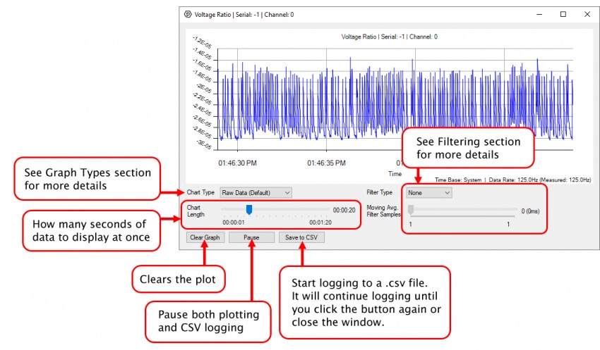
If you need more complex functionality such as logging multiple sensors to the same sheet or performing calculations on the data, you'll need to write your own program. Generally this will involve addressing the correct channel, opening it, and then creating an Event Handler and adding graphing/logging code to it.
The quickest way to get started is to download some sample code for your desired programming language and then search google for logging or plotting in that language (e.g. "how to log to csv in python") and add the code to the existing change handler.
Filtering
You can perform filtering on the raw data in order to reduce noise in your graph. For more information, see the Control Panel Graphing page.
Graph Type
You can perform a transform on the incoming data to get different graph types that may provide insights into your sensor data. For more information on how to use these graph types, see the Control Panel Graphing page.
Firmware Upgrade
MacOS users can upgrade device firmware by double-clicking the device row in the Phidget Control Panel.
Linux users can upgrade via the phidget22admin tool (see included readme for instructions).
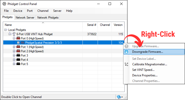
Windows users can upgrade the firmware for this device using the Phidget Control Panel as shown below.
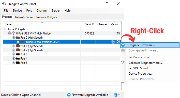
Firmware Downgrade
Firmware upgrades include important bug fixes and performance improvements, but there are some situations where you may want to revert to an old version of the firmware (for instance, when an application you're using is compiled using an older version of phidget22 that doesn't recognize the new firmware).
MacOS and Linux users can downgrade using the phidget22admin tool in the terminal (see included readme for instructions).
Windows users can downgrade directly from the Phidget Control Panel if they have driver version 1.9.20220112 or newer:
Firmware Version Numbering Schema
Phidgets device firmware is represented by a 3-digit number. For firmware patch notes, see the device history section on the Specifications tab on your device's product page.
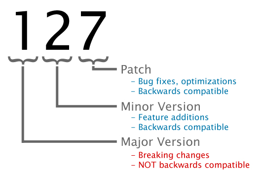
- If the digit in the 'ones' spot changes, it means there have been bug fixes or optimizations. Sometimes these changes can drastically improve the performance of the device, so you should still upgrade whenever possible. These upgrades are backwards compatible, meaning you can still use this Phidget on a computer that has Phidget22 drivers from before this firmware upgrade was released.
- If the digit in the 'tens' spot changes, it means some features were added (e.g. new API commands or events). These upgrades are also backwards compatible, in the sense that computers running old Phidget22 drivers will still be able to use the device, but they will not be able to use any of the new features this version added.
- If the digit in the 'hundreds' spot changes, it means a major change has occurred (e.g. a complete rewrite of the firmware or moving to a new architecture). These changes are not backwards compatible, so if you try to use the upgraded board on a computer with old Phidget22 drivers, it will show up as unsupported in the Control Panel and any applications build using the old libraries won't recognize it either. Sometimes, when a Phidget has a new hardware revision (e.g. 1018_2 -> 1018_3), the firmware version's hundreds digit will change because entirely new firmware was needed (usually because a change in the processor). In this case, older hardware revisions won't be able to be upgraded to the higher version number and instead continue to get bug fixes within the same major revision.
To interface a switch with the DAQ1200, simply connect the switch across the input and ground terminals for a channel.
The DAQ1200 can also detect signals from 5V logic level devices. Be aware that the input is active-low, which means that LOW voltages will be detected as TRUE, and HIGH voltages as FALSE.
In some applications, particularly where there is a lot of electrical noise (automotive), or where you want maximum protection of the circuitry (interactive installations, kiosks), electrical isolation buys you a huge margin of protection.
If wired according to the diagram, driving the LED will cause the DAQ1200 to report TRUE.
Note that in cases where many isolated inputs are required, or for simplicity's sake, you may want to consider using the DAQ1300 or DAQ1301, which are (more sophisticated) ready-made isolated digital input Phidgets.