1121 User Guide: Difference between revisions
No edit summary |
|||
| Line 3: | Line 3: | ||
===Required Hardware=== | ===Required Hardware=== | ||
* A 1121 Voltage Divider | * A [{{SERVER}}/products.php?product_id=1121 1121 Voltage Divider] | ||
* An InterfaceKit or Hub to read the sensor | * An InterfaceKit or Hub to read the sensor | ||
* A Phidget cable | * A Phidget cable | ||
Revision as of 16:16, 6 June 2017
Required Hardware
- A 1121 Voltage Divider
- An InterfaceKit or Hub to read the sensor
- A Phidget cable
- A USB cable
- A computer
- A variable resistance sensor
Connecting the Pieces
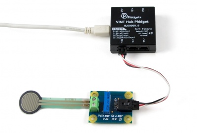
- Connect the voltage divider to the InterfaceKit or Hub with the Phidget cable.
- Connect a variable resistance sensor to the terminal block on the voltage divider. Polarity doesn't matter.
- Connect the InterfaceKit or Hub to your computer with the USB cable.
Testing Using Windows
Phidget Control Panel
In order to demonstrate the functionality of the 1018, the Phidget Control Panel running on a Windows machine will be used.
The Phidget Control Panel is available for use on both macOS and Windows machines.
Windows
To open the Phidget Control Panel on Windows, find the ![]() icon in the taskbar. If it is not there, open up the start menu and search for Phidget Control Panel
icon in the taskbar. If it is not there, open up the start menu and search for Phidget Control Panel
macOS
To open the Phidget Control Panel on macOS, open Finder and navigate to the Phidget Control Panel in the Applications list. Double click on the ![]() icon to bring up the Phidget Control Panel.
icon to bring up the Phidget Control Panel.
For more information, take a look at the getting started guide for your operating system:
Linux users can follow the getting started with Linux guide and continue reading here for more information about the 1018.
First Look
After plugging the 1018 into your computer and opening the Phidget Control Panel, you will see something like this:
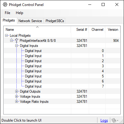
The Phidget Control Panel will list all connected Phidgets and associated objects, as well as the following information:
- Serial number: allows you to differentiate between similar Phidgets.
- Channel: allows you to differentiate between similar objects on a Phidget.
- Version number: corresponds to the firmware version your Phidget is running. If your Phidget is listed in red, your firmware is out of date. Update the firmware by double-clicking the entry.
The Phidget Control Panel can also be used to test your device. Double-clicking on an object will open an example.
Voltage Input
Double-click on a Voltage Input object in order to run the example: [[Image:{{{1}}}_VoltageInputSensor_Example.jpg|center|link=]]
General information about the selected object will be displayed at the top of the window. You can also experiment with the following functionality:
- Modify the change trigger and/or data interval value by dragging the sliders. For more information on these settings, see the data interval/change trigger page.
- If you have an analog sensor connected that you bought from us, you can select it from the Sensor Type drop-down menu. The example will then convert the voltage into a more meaningful value based on your sensor, with units included, and display it beside the Sensor Value label. Converting voltage to a Sensor Value is not specific to this example, it is handled by the Phidget libraries, with functions you have access to when you begin developing!
For more information about Voltage Inputs, check out the Voltage Input Primer.
Testing Using macOS
- Go to the Quick Downloads section on the macOS page.
- Download and run the Phidget macOS Installer
- Click on System Preferences >> Phidgets (under Other) to activate the Preference Pane
- Make sure your device is properly attached
- Double click on your device's objects in the listing to open them. The Preference Pane and examples will function very similarly to the ones described above in the Windows section.
Testing Using Linux
For a general step-by-step guide on getting Phidgets running on Linux, see the Linux page.
Using a Remote OS
We recommend testing your Phidget on a desktop OS before moving on to remote OS. Once you've tested your Phidget, you can go to the PhidgetSBC, or iOS pages to learn how to proceed.
Technical Details
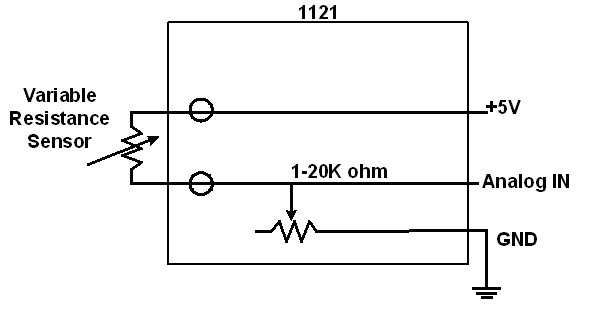
Configuring the Voltage Divider
Why is adjusting the resistance important? The Analog Input can measure a voltage between 0V and 5V. When using variable resistance devices a voltage divider is commonly used to measure the changing resistance. The two resistors in the divider form a voltage, based on the ratio between them. This voltage is then measured by the Analog Input. To optimize the voltage divider to meet your needs, you have to adjust the fixed resistance to match the characteristics of your chosen sensor. To adjust the resistance on the Voltage Divider, simply turn the screw on the potentiometer clockwise to decrease the resistance and counterclockwise to increase it. You'll see a change in resistance of about 900 to 1000 ohms per revolution. First, adjust the resistance for no stimuli on your sensor and then apply the maximum possible stimuli and make sure that sensor's voltage stays within a range that gives you acceptable resolution. At the extremes (less than 0.25V or greater than 4.75V), a very large change in stimuli (and therefore change in the resistance) produces only a small change in voltage. Keep adjusting until you get a range you are happy with.
Non-Phidgets Sensors
Here is a list of interesting variable resistance sensors that could be used with the Voltage Divider.
Light Sensors:
Light Sensors - CDS Photocells (Advanced Photonics)
Search for “photocell”
Examples - “PDV-P9003-1”
Force Sensors
Force Sensors (CUI Inc.)
Search for “force sensor”
Examples - “IESP-12”
http://www.trossenrobotics.com
Force Sensing FSRs
Thermistors
Search Digikey for ‘Thermistor Radial’
Choose a thermistor with a resistance in the range 10K ohms.
Bend sensor
Phidget Cable
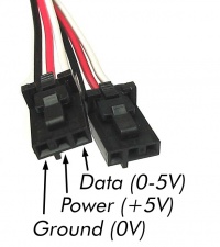
The Phidget Cable is a 3-pin, 0.100 inch pitch locking connector. Pictured here is a plug with the connections labelled. The connectors are commonly available - refer to the Analog Input Primer for manufacturer part numbers.
What to do Next
- Programming Languages - Find your preferred programming language here and learn how to write your own code with Phidgets!
- Phidget Programming Basics - Once you have set up Phidgets to work with your programming environment, we recommend you read our page on to learn the fundamentals of programming with Phidgets.