Spatial Guide
Spatial Sensors and Their Uses
Introduction to AHRS
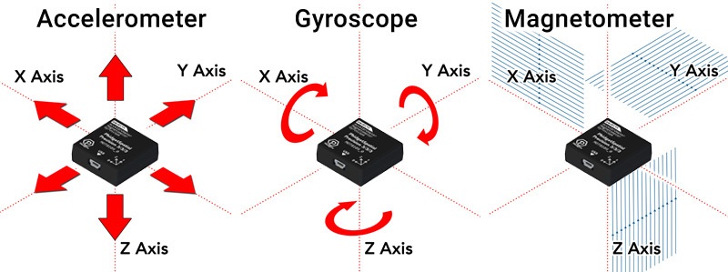
Spatial sensors from Phidgets use AHRS (Attitude and Heading Reference System) algorithms to combine data from accelerometers, magnetometers and gyroscopes into a calculation of the device’s orientation more precise than could be achieved by any of the sensors individually.
While this process is by no means straightforward, PhidgetSpatial sensors come with built-in AHRS calculations combining data from all three types of sensors out of the box. By using the Phidget Spatial object in your code, you can get a direct reading of the heading of your device, in both Euler angle and Quaternion form.
Euler Angles
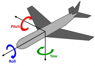
Euler angles are a measure of an object’s orientation in the form of pitch, roll, and yaw angles. The advantage of Euler angles in denoting heading is that they are relatively easy to visualise. You can get the Euler angles of your sensor directly from the Phidgets library.
While they are a human-friendly way of denoting overall orientation, we strongly recommend against using Euler angles in post-processing calculations, as they can be susceptible to problems of gimbal lock. For applications requiring more adjustments than a simple heading offset, we recommend using quaternions.
Quaternions
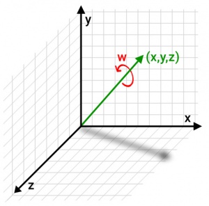
For applications that require more complex analysis, PhidgetSpatial devices also provide the orientation of the device using quaternions. Quaternions are a more mathematically complete way of denoting orientation and rotations of a system. For what they lose in intuitiveness, the advantage of quaternions is that they can be used in any number of complex calculations without the risk of the aforementioned gimbal lock.
For most practical purposes, it helps to remember that quaternions are not meant to be visualized, or dealt with directly. Instead, any program or library that uses them will have functions to perform calculations with them behind the scenes. If you don’t yet have such a library in your program, but need to use quaternions, we recommend finding one, rather than wading through the math yourself. In this way, while they are difficult to visualize, you can at least remain comfortable in the knowledge that one does not often need to fully understand quaternions to use them in an application.
Quaternions tend to be the preferred rotation system for programs that deal with 3D objects, like Unity, and their inclusion as an output directly from a PhidgetSpatial is designed to make sensor integration as seamless as possible.
What Does AHRS Actually Do?
The AHRS algorithm on Phidgets uses an accelerometer and a magnetometer to keep track of heading over long timescales. When the device is perceived to be at rest, the heading and gyroscopes are gradually aligned and zeroed to reflect that the device is not moving, and pointed towards combined direction from the magnetometer and accelerometer readings. When the device is in motion, the AHRS algorithm starts relying more heavily on the gyroscope for angular rotations, since the accelerometer may no longer be pointing straight down, and the field from the compass may be in flux. By adjusting how much the device relies on the gyroscope in place of the accelerometer and magnetometer, a smoother and more accurate profile of the device’s orientation can be achieved than by using any of the sensors alone.
Temperature Stabilization
Electronic accelerometers and gyroscopes are sensitive to changes in temperature to a small but measurable degree. For cases where long term accuracy is a priority, some of our Spatial sensors have a temperature stabilization feature which allows the boards to heat themselves up to a pre-defined constant temperature (typically 45 or 50°C) to reduce or eliminate drift due to temperature effects.
When using the temperature stabilization feature, it is very important to wait for the board to be fully heated and settled before use, as the process of heating the board will change the sensor readings as the temperature rises to the target. Phidgets that allow temperature stabilization are calibrated at their target temperature, so the sensors will produce more accurate results once heated.
If you are using a temperature-stabilized spatial sensor, it is also very important to keep the board in its enclosure or otherwise insulated from outside air, as air moving directly over the warmed sensors will cause worse results than if the board was not heated at all.
Demonstrations Using the Control Panel Example
Note: If your control panel example does not resemble the following, be sure to update your Phidget Control Panel.
If your example still doesn't match, your Spatial Phidget is likely too old to support built-in AHRS calculations.
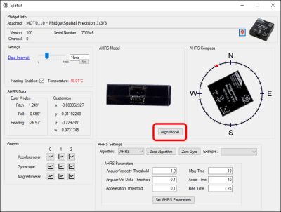
The spatial example gives you a way to directly visualize the results from the AHRS algorithm used on Phidget Spatial sensors. We recommend using this example with the sensor in hand at your desk to help visualize the effectiveness of the algorithm.
The first thing you might notice is that the model doesn’t appear to match the orientation of the spatial in your hand. To make the AHRS model line up with your physical spatial, point the wire at the screen and click Align Model. Your spatial model should now mirror the movements of the spatial in your hand.
The AHRS compass drawing is also provided as a visual indicator of the Heading, independent of the screen location. Notice that the compass bearing indicates north when the left-hand side of the Phidget is pointed north.
If your sensor has a heating option, be sure to check the Heating Enabled box, and wait until the temperature reading stays green for best results. In your own programs, wait until the temperature reaches 45C, and then if possible give the sensor an additional minute or two to ensure the whole board is evenly heated.
AHRS Settings
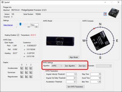
Now we can look at the AHRS settings panel:
Algorithm
The algorithm setting dictates whether or not the compass is going to be factored into calculations.
- AHRS: When setting Algorithm to AHRS (the default setting) heading is gradually re-aligned with the compass over time, and all headings will be relative to magnetic north. When you Zero the AHRS algorithm, it will forcibly realign the heading to the compass reading.
- IMU: When using IMU, the compass readings are ignored, and a heading of 0° corresponds to the direction the device was facing when it was started, or where it was last zeroed. By clicking the Zero Algorithm button, it will realign all calculations to reference the direction it is currently facing as the new 0° heading.
Zero Algorithm
The Zero Algorithm button centers the algorithm’s heading either on the compass reading or on the direction it is currently facing (see AHRS Mode). The accumulated gyro biases will also be dropped, reverting to the raw (zeroed) gyro measurements. Note that the initial position in AHRS mode can vary by a couple degrees initially, due to noise inherent in the compass measurements. Click Zero Algorithm a few times now to see this for yourself. This noise will be averaged out by the rest of the algorithm, and it should settle into a consistent position after a couple seconds.
If you find the model is drifting more than 2-3 degrees immediately after Zeroing the algorithm (while the spatial is staying still) you may want to try zeroing the gyroscope for better results.
Zero Gyro
Before zeroing the gyroscope, ensure it is securely at rest. Zeroing the gyroscope will average the gyroscope’s readings for a second or two, and automatically subtract the result from subsequent measurements. This is a way to combat drift in the gyros, and we recommend finding a way to zero the gyros before starting AHRS calculations. The results of zeroing the gyro will only persist for as long as it remains open.
If explicitly zeroing the gyro is not practical in your application, you can consider running the AHRS algorithm briefly with a wide Angular Velocity Threshold, then narrowing said threshold again once the system has a chance to compensate for drift on its own.
AHRS Parameters
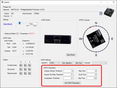
The AHRS parameters are used to determine certain characteristics of your system so the AHRS algorithm can make better assumptions about the movement in your system. Each of these parameters will have recommended values as a starting point for your Phidget in a table below.
All AHRS settings will apply to a system using the IMU algorithm in exactly the same ways, except the compass readings and related settings will be ignored when using IMU.
Angular Velocity Threshold
This is the minimum reading from your gyroscopes that the device will use to assume the device is at rest. While the device assumes it is at rest, it will gradually adjust towards making the current gyro readings the new “zero”, compensating for drift over time. This value can be significantly lower if you have zeroed your gyroscope before zeroing the algorithm, as the pre-existing drift of the gyros will have been accounted for. Otherwise, this value will need to be large enough to overcome any pre-existing offsets in your gyro.
The closer you can set this value to zero, the slower the device needs to turn (or think it’s turning) to stop adjusting the gyro biases. If this value is too high, the gyros can be biased away from what is truly stationary. If this value is too low, the gyros will never adjust their bias, and you will see drift over time.
Angular Velocity Delta Threshold
This is the minimum change between gyroscope samples before the gyro stops thinking it’s at rest. You can get a good value for this from the gyroscope example after installing the gyro in your application. Simply open the graphs for all axes, and set this value near the peak-to-peak noise.
If this value is too low, the device will never think it's at rest. If it's too high, certain vibrations could affect your gyro biases (though the effects of these may also be limited by the Angular Velocity Threshold).
Acceleration Threshold
The minimum measured acceleration your system will assume it is at rest, minus gravity. This value is also used to determine how much motion is accepted before the device begins to ignore the acceleration vector as a reliable source of “down”, and relies entirely on the gyros for pitch and roll until the device stops again. Again, you can use the noise in the graphs from your accelerometer example to get a baseline of the noise, and choose a value accordingly.
If this value is too high, your device can adjust to thinking “down” is the wrong direction, or be swayed by fast motions. If this value is too low, the device may never think it is at rest to begin the process of correcting its pitch and roll.
Mag Time
The amount of time (in seconds) your system will take to re-adjust the heading 95% of the way to aligning with the compass bearing, for differences in compass bearing and AHRS heading less than 15 degrees. Outside of 15 degrees of error, this is the time it will take the AHRS heading to correct towards the compass bearing by 45 degrees, to help limit adverse effects of interference. The better the gyros in your system, the higher this value can be.
By setting this value higher your device can become more (but never entirely) resistant to magnetic interference, at the expense of placing more weight on accurate gyroscope readings. By setting this value lower, the device’s orientation will more quickly adjust to the magnetic field readings. If this value is low enough, white noise in your compass readings will begin to show up in your measured heading.
Accel Time
The amount of time (in seconds) your system will take to realign your pitch and roll to the acceleration vector, once the device believes it is at rest. The better the gyros in your system, the higher this value can be.
By setting this value higher your device can become more resistant to acceleration affecting orientation, at the expense of placing more weight on accurate gyroscope readings. By setting this value lower, the device’s orientation will more quickly adjust to the accelerometer readings (limited by the above Acceleration Threshold).
Bias Time
If the sensor is deemed to be at rest, a “bias” parameter internal to the algorithm is slowly added to the gyroscope to compensate for any drift. Effectively, this will automatically gradually zero the gyro readings internal to the algorithm, reducing or eliminating the effects of drift. The time specified here (in seconds) is the time it takes to adjust the bias parameters to compensate for 95% of the gyro’s offsets once the device is at rest.
The speed the gyros should be biased is a balance between getting a solid average and having the zeroing occur quickly enough that biases can be fully compensated for during short periods or rest.
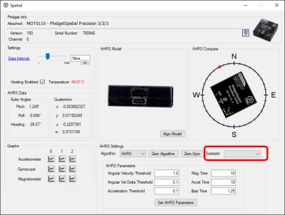
Example
To get the best precision we recommend tuning these parameters as best fits your application. However, we have provided some sample values to make a couple demonstrations, and to give you some idea of how to adapt these parameters to certain situations.
To more easily set up these example cases, this dropdown provides a list of settings for generic cases, and demonstrations of how you might adapt these values to certain scenarios.
General Purpose
A set of values selected for your device that should work “well enough” out of the box for simple situations, such as moving the device around with your hand.
No Gyro
To demonstrate why gyroscopes are an essential part of AHRS, we’ve given some settings that will effectively ignore any input from the gyroscopes, and snap to the magnetometer and accelerometer readings alone. You will notice this is incredibly noisy, especially if you start moving the sensor around.
We do not recommend using these settings in practice.
All Gyro
For completeness, we have included a selection to set AHRS to more or less ignore input from the magnetometers and accelerometers. By selecting this sample, you can see how the gyroscopes will drift over time and fast motions, clearly demonstrating the need for the accelerometer and magnetometer to bring the gyros back into alignment.
We do not recommend using these settings in practice.
Zeroed
If you are able to zero your gyroscopes, and your application is relatively free of vibrations, you should be able to use a narrower Angular Velocity Threshold. As a result, you may also be able to relax the Mag Time and Accel Time parameters, since you can better trust that the gyroscopes will only be re-biased when they are truly not rotating.
High Vibrations
Regardless of whether or not you can zero your gyroscope, if your system suffers from constant large vibrations, the AHRS thresholds will have to be relaxed to allow the gyros to be biased at all. In doing so, we also raise the Accel Time, not because we can trust the gyroscopes more in this scenario, but rather because we must trust the accelerometer less. Assuming there is little magnetic noise, Mag Time can be decreased to snap the heading closer to the magnetic field.
Suggested Parameters
| Angular Velocity Threshold | Angular Vel Delta Threshold | Acceleration Threshold | Mag Time | Accel Time | Bias Time | |
|---|---|---|---|---|---|---|
| MOT1102 | 2.0 | 0.6 | 0.1 | 5 | 5 | 1.25 |
| MOT0110 Out of the Box |
1.0 | 0.1 | 0.05 | 10 | 10 | 1.25 |
| MOT0110 Heated and Zeroed |
0.5 | 0.1 | 0.05 | 120 | 120 | 1.25 |
Choosing a Phidget Spatial
The Spatial Phidget you use in your application will depend on how accurate certain aspects of your measurement need to be. To simplify the decision, we can narrow this down to various kinds of applicaitons:
| Applicaiton | Phidget |
|---|---|
| Navigation or Outdoor Usage | MOT0110 PhidgetSpatial Precision 3/3/3 |
| Gestures and Qualitative Effects | MOT1102 Spatial Phidget |
FAQ
Why does the Euler Angle for pitch never exceed 90 degrees?
The Euler Angles provided by the Phidgets library are calculated directly from a corresponding quaternion. They do not take into account past movements, so the orientation of a board that passes 90 degrees in pitch can just as easily be represented by a pitch of less than 90 degrees, with different roll and heading parameters. This is one reason why Euler Angles are not recommended for use in serious calculations, in favor of using the corresponding quaternions.
Why do the Euler Angle readings stop working as well near 90 degrees of pitch?
This is actually a good example of gimbal lock, and why it is not advised to use Euler Angles in calculation. When pitch approaches 90 degrees, the roll and yaw axes start to line up, which makes it hard to distinguish one from the other. In other words, at 90 degrees of pitch, a change in roll could just as easily be a change in heading, and vice-versa. This is another reason we recommend quaternions for all serious calculations.