|
Notice: This page contains information for the legacy Phidget21 Library. Phidget21 is out of support. Bugfixes may be considered on a case by case basis. Phidget21 does not support VINT Phidgets, or new USB Phidgets released after 2020. We maintain a selection of legacy devices for sale that are supported in Phidget21. We recommend that new projects be developed against the Phidget22 Library.
|
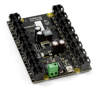
1032 User Guide
| |
| Go to this device's product page |
Getting Started
Checking the Contents
|
You should have received:
|
In order to test your new Phidget you will also need:
| |
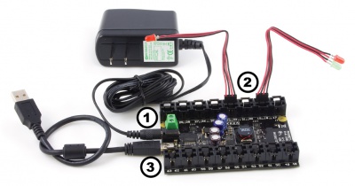
Connecting the Pieces
|
| |
Testing Using Windows 2000 / XP / Vista / 7
Make sure you have the current version of the Phidget library installed on your PC. If you don't, follow these steps:
- Go to the Quick Downloads section on the Windows page
- Download and run the Phidget21 Installer (32-bit, or 64-bit, depending on your system)
- You should see the
 icon on the right hand corner of the Task Bar.
Running Phidgets Sample Program
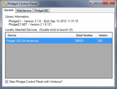
Double clicking on the ![]() icon loads the Phidget Control Panel; we will use this program to ensure that your new Phidget works properly.
icon loads the Phidget Control Panel; we will use this program to ensure that your new Phidget works properly.
The source code for the LED-full sample program can be found in the quick downloads section on the C# Language Page. If you'd like to see examples in other languages, you can visit our Languages page.
Updating Device Firmware
If an entry in this list is red, it means the firmware for that device is out of date. Double click on the entry to be given the option of updating the firmware. If you choose not to update the firmware, you can still run the example for that device after refusing.
|
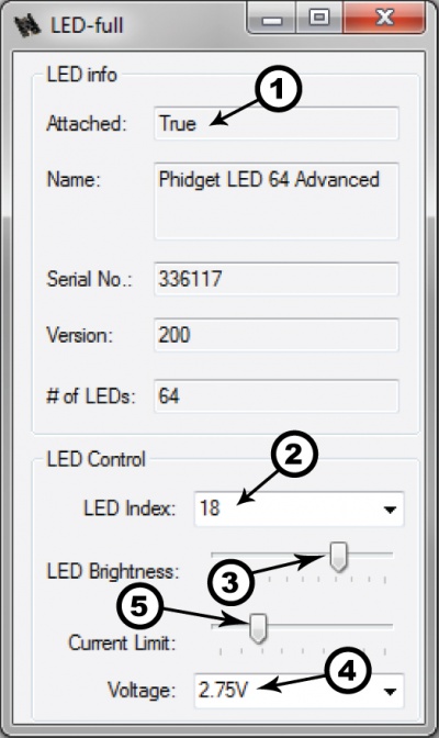
Double Click on the |
| |
Note: Using the current slider could cause false temperature warnings and errors to be reported. To avoid seeing these warnings, set the current limit once and use the brightness slider to change the brightness of the LEDs rather than changing the current limit. |
|
Testing Using Mac OS X
- Go to the Quick Downloads section on the Mac OS X page
- Download and run the Phidget OS X Installer
- Click on System Preferences >> Phidgets (under Other) to activate the Preference Pane
- Make sure that the Phidget LED 64 Advanced is properly attached.
- Double Click on Phidget LED 64 Advanced in the Phidget Preference Pane to bring up the LED-full Sample program. This program will function in a similar way as the Windows version.
Using Linux
For a step-by-step guide on getting Phidgets running on Linux, check the Linux page.
Using Windows Mobile / CE 5.0 / CE 6.0
For a step-by-step guide on getting Phidgets running on Windows CE, check the Windows CE page.
Technical Details
The 1032 uses four controller chips that allow you to vary the current and voltage supplied to each channel. It uses pulse-width modulation to vary the brightness of each LED.
Multiple LEDs on a Single Channel
You can have multiple LEDs hooked up to a single channel on the 1032, (for example, a short string of LEDs) to reduce the amount of wiring, although keep in mind that you'll lose control of the individual lights, and can only toggle or dim the entire string. When using multiple LEDs on a single channel, you'll need to increase the voltage limit for that channel. If the LEDs are too dim at the maximum voltage, you should spread them out to other channels.
High-Current Considerations
If you're using high-current LEDs, you should spread your load evenly across the board to avoid having one of the controller chips overheat. There are four controller chips, each controlling the channels on a quarter of the board.
Controller 1: 0, 1, 2, 3, 4, 5, 6, 7, 24, 25, 26, 27, 28, 29, 30, 31
Controller 2: 8, 9, 10, 11, 12, 13, 14, 15, 16, 17, 18, 19, 20, 21, 22, 23
Controller 3: 32, 33, 34, 35, 36, 37, 38, 39, 56, 57, 58, 59, 60, 61, 62, 63
Controller 4: 40, 41, 42, 43, 44, 45, 46, 47, 48, 49, 50, 51, 52, 53, 54, 55
Board Connector Diagram
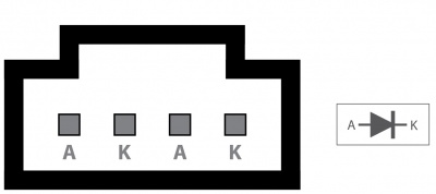
The connector used on the 1032 LED board is a Molex 70543-0003. The mating connector used on our LED cables is the Molex 50-57-9404.
Heat Dissipation and Thermal Protection
Projects that require a high supply voltage, or have a lot of heat being produced from over voltage settings, will have over-temperature problems. This can be mitigated somewhat by understanding how channels are grouped and how the heat is distributed around the controller. On the 1032 channels are split into four groups: (0-7,24-31), (8-23), (32-39, 56-63) and (40-55); each controlled by their own individual IC. Evenly distributing the LEDs that may produce a lot of heat across these groups will balance the load on the ICs and reduce the risk of thermal overload. When thermal overload occurs, the integrated circuit (IC) controlling the involved LEDs will disable the output of all the channels it controls. For example, if an over-temperature occurs due to channel 12, all of the channels 8 through 23 will be disabled by the IC until the temperature back within the operating range. Thermal protection is activated when the die of the IC reaches approximately 160 degrees Celsius. Once the over-temperature fault has been corrected (ie, the IC has cooled down), the output channels will be re-enabled with the same settings as before the thermal shutdown. An error message will be produced during an over-temperature.
Further Reading
For more information, take a look at the LED Primer.
API
We document API Calls specific to this product in this section. Functions common to all Phidgets and functions not applicable to this device are not covered here. This section is deliberately generic. For calling conventions under a specific language, refer to the associated API manual in the Quick Downloads section for that language. For exact values, refer to the device specifications.
Functions
int LEDCount() [get] : Constant
- Returns the number of LEDs that this board can drive. This may not correspond to the actual number of LEDs attached.
double Brightness(int LEDIndex) [get,set]
- Sets/Gets the brightness of an LED. Valid values are 0-100, with 0 being off and 100 being the brightest. This 0-100 value is converted internally to an 12-bit value (0-4095).
int CurrentLimitIndexed(int LEDIndex) [get,set]
- Sets/Gets the current limit of an LED. Valid current limits range from 0 to 80mA. The default current limit is 20mA.
int Voltage() [get,set]
- Sets/Gets the output voltage. Valid voltages are 1.7V, 2.75V, 3.9V and 5V, these will generally be delimited with an enumerator where possible, or an integer where not. The default voltage is 2.75V.
Events
Error(String errorDescription, int errorCode) [event]
- 1032 uses the generic error event to stream back fault conditions. The fault can be identified by the errorDescriptionstring. The only fault currently reported is Thermal Shutdown (TSD).
Product History
The 1032 - PhidgetLED-64 replaced our previous LED controller, the 1031 - PhidgetLED-64.
| Date | Board Revision | Device Version | Comment |
|---|---|---|---|
| January 2013 | 0 | 200 | Product Release |
| October 2015 | 0 | 201 | OS X El Capitan USB bug fix |