Products for USB Sensing and Control

Replaced by the 3052_1 - SSR Relay Board 2.5A.
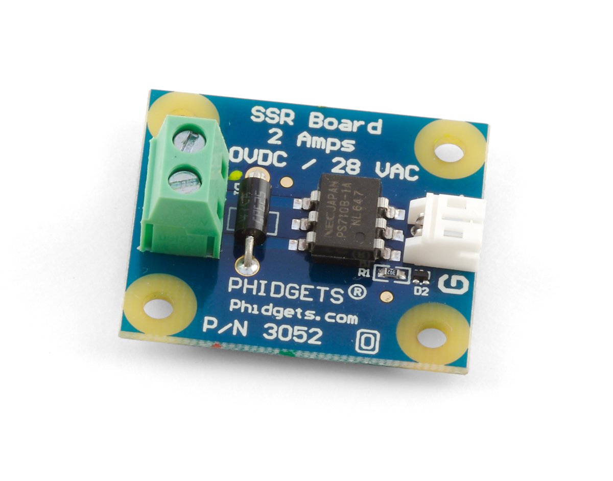
Solid State Relays, or SSRs, are devices designed to operate like standard relays but without mechanical motion.
The SSR Board is safe to use with sensitive control devices like microprocessors, and will not damage a Phidget device or your PC. Optoisolation between the control inputs and outputs of the SSR in the form of a GaAs LED paired with a set of optically-controlled MOSFETs provides protection from output to input. An on-board 47V bidirectional transorb across the relay output protects the board from static electricity and surges from inductive loads.
| Electrical Properties | |
|---|---|
| Relay Output Type | MOSFET |
| Isolation Method | Photoelectric |
| Dielectric Strength | 1.5 kV AC |
| Control Voltage Min | 1.5 V DC |
| Control Voltage Max | 5 V DC |
| Load Voltage Max (DC) | 40 V DC |
| Load Voltage Max (AC) | 28 V AC |
| Load Current Max (AC) | 2.5 A |
| Load Current Max (DC) | 2.5 A |
| Turn-on Time Max | 5 ms |
| Turn-off Time Max | 0.2 ms |
| Contact Resistance Max | 50 mΩ |
| Physical Properties | |
| Recommended Wire Size (Load) | 12 - 24 AWG |
| Operating Temperature Min | -40 °C |
| Operating Temperature Max | 85 °C |
| Customs Information | |
| Canadian HS Export Code | 8473.30.00 |
| American HTS Import Code | 8473.30.51.00 |
| Country of Origin | CN (China) |
If you only need to switch 0.5A or less, you should take a look at the 3054 - SSR Relay Board 0.5A .
If you need two relays to switch up to 9amps you should consider the 3053 - Dual SSR Relay Board.
You can protect your board by purchasing the 3821 - Acrylic Enclosure for the 3052.
| Date | Board Revision | Device Version | Comment |
|---|---|---|---|
| October 2007 | 0 | N/A | Product Release |
| October 2007 | 1 | N/A | Replaced connector w/ terminal blocks |
Welcome to the 3052 user guide! In order to get started, make sure you have the following hardware on hand:
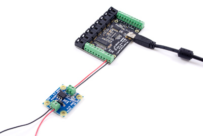
Next, you will need to connect the pieces:
Now that you have everything together, let's start using the 3052!
In order to demonstrate the functionality of the 3052, we will connect it to the 1018, and then run an example using the Phidget Control Panel on a Windows machine.
The Phidget Control Panel is available for use on both macOS and Windows machines. If you would like to follow along, first take a look at the getting started guide for your operating system:
Linux users can follow the getting started with Linux guide and continue reading here for more information about the 3052.
After plugging in the 3052 into the 1018, and the 1018 into your computer, open the Phidget Control Panel. You will see something like this:
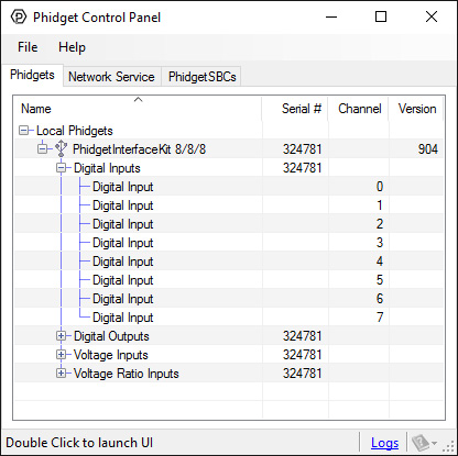
The Phidget Control Panel will list all connected Phidgets and associated objects, as well as the following information:
The Phidget Control Panel can also be used to test your device. Double-clicking on an object will open an example.
Double-click on a Digital Output object in order to run the example:
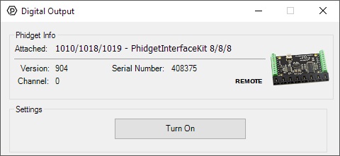
General information about the selected object will be displayed at the top of the window. You can also experiment with the following functionality:
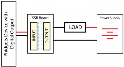
Solid State Relays, or SSRs, are devices designed to operate like standard relays but without mechanical motion. Built instead out of silicon transistors, SSRs allow currents and voltages to be switched by simple digital signals from a microprocessor or any other device that can supply the small amount of current needed to activate the SSR’s internal switching mechanism. For more information on solid state relays, refer to the SSR Guide.
The 3052 is safe to use with sensitive control devices like microprocessors, and will not damage a Phidget or your PC. Optoisolation between the control inputs and outputs of the SSR in the form of a GaAs LED paired with a set of optically-controlled MOSFETs provides protection from output to input. An on-board 47V bidirectional transorb across the relay output protects the board from static electricity and surges from inductive loads.
Using the SSR Relay Board in your application is typically done according to the diagram below, though there are other implementations for it as well.