|
Notice: This page contains information for the legacy Phidget21 Library. Phidget21 is out of support. Bugfixes may be considered on a case by case basis. Phidget21 does not support VINT Phidgets, or new USB Phidgets released after 2020. We maintain a selection of legacy devices for sale that are supported in Phidget21. We recommend that new projects be developed against the Phidget22 Library.
|
1011 User Guide
Getting Started
Checking the Contents
|
You should have received:
|
In order to test your new Phidget you will also need:
| |
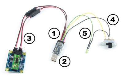
Connecting the Pieces
|
| |
Testing Using Windows 2000 / XP / Vista / 7
Make sure you have the current version of the Phidget library installed on your PC. If you don't, follow these steps:
- Go to the Quick Downloads section on the Windows page
- Download and run the Phidget21 Installer (32-bit, or 64-bit, depending on your system)
- You should see the
 icon on the right hand corner of the Task Bar.
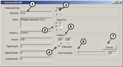
Running Phidgets Sample Program
Double clicking on the ![]() icon loads the Phidget Control Panel; we will use this program to ensure that your new Phidget works properly.
icon loads the Phidget Control Panel; we will use this program to ensure that your new Phidget works properly.
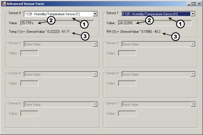
The source code for the InterfaceKit-Full sample program can be found in the quick downloads section on the C# Language Page. If you'd like to see examples in other languages, you can visit our Languages page.
Updating Device Firmware
If an entry in this list is red, it means the firmware for that device is out of date. Double click on the entry to be given the option of updating the firmware. If you choose not to update the firmware, you can still run the example for that device after refusing.
|
Double Click on the |

| |
|
|
|
| |
Testing Using Mac OS X
- Go to the Quick Downloads section on the Mac OS X page
- Download and run the Phidget OS X Installer
- Click on System Preferences >> Phidgets (under Other) to activate the Preference Pane
- Make sure that the is properly attached.
- Double Click on in the Phidget Preference Pane to bring up the Sample program. This program will function in a similar way as the Windows version.
Using Linux
For a step-by-step guide on getting Phidgets running on Linux, check the Linux page.
Using Windows Mobile / CE 5.0 / CE 6.0
For a step-by-step guide on getting Phidgets running on Windows CE, check the Windows CE page.
Technical Details
I/O Wiring Diagram
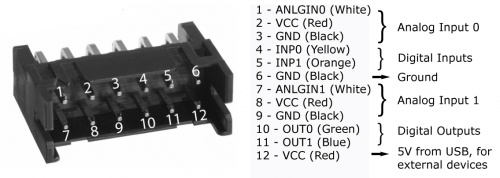
Replacing the I/O Interface Cable
If your I/O interface cable gets damaged, you can remove it and replace it with 3013 - PhidgetInterfaceKit 2/2/2 Replacement Cable. Pull hard on the connector until it comes out.
You can also remove individual wires from the cable if they are not needed. Detach the wire assembly from the 1011, delicately pry up the plastic tab with a small flat-head screwdriver, and pull out the wire. This should only be done for wires that you never plan on needing as it is very easy to break the plastic tab.
Warning: The cable has been designed to be permanently attached to the 1011. We strongly recommend that you limit the number of times you remove the wire assembly from the 1011 to as few times as possible since repeated removals and insertions will eventually damage both connectors.
API
We document API Calls specific to this product in this section. Functions common to all Phidgets and functions not applicable to this device are not covered here. This section is deliberately generic. For calling conventions under a specific language, refer to the associated API manual in the Quick Downloads section for that language. For exact values, refer to the device specifications.
Data Structures
Functions
Events
Product History
| Date | Board Revision | Device Version | Comment |
|---|---|---|---|