|
Notice: This page contains information for the legacy Phidget21 Library. Phidget21 is out of support. Bugfixes may be considered on a case by case basis. Phidget21 does not support VINT Phidgets, or new USB Phidgets released after 2020. We maintain a selection of legacy devices for sale that are supported in Phidget21. We recommend that new projects be developed against the Phidget22 Library.
|
Solid State Relay Primer: Difference between revisions
No edit summary |
|||
| (135 intermediate revisions by 5 users not shown) | |||
| Line 1: | Line 1: | ||
[[Category: Primer]] | |||
{| | {| | ||
|- valign=middle | |- valign=middle | ||
| align=center width=300px| __TOC__ | | align=center width=300px| __TOC__ | ||
| [[Image:SSR.jpg]] | | [[Image:SSR.jpg|link=]] | ||
| [[Image:3052.jpg|200px]] | | [[Image:3052.jpg|link=|200px]] | ||
|} | |} | ||
==Introduction== | ==Introduction== | ||
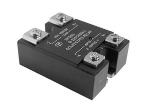
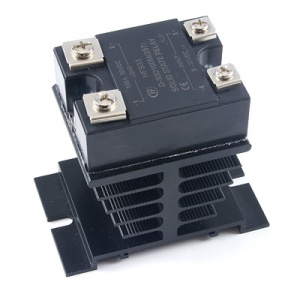
They perform the same job as [[Mechanical Relay Primer|Mechanical Relays]], but have the following advantages: | [[Image:SSR.jpg|thumb|link=|A "hockey puck" SSR, so named because of its thick shape and black color. They are specifically designed to switch either AC loads or DC loads, but never both.]] | ||
* SSRs produce less electromagnetic interference during operation, | |||
* The switch contacts of a mechanical relay will eventually wear down from | Solid state relays (SSRs) turn on or off the power being supplied to other devices, in a similar fashion as a physical switch. However, instead of being switched by human interaction like a physical switch, SSRs are switched electronically. | ||
With SSRs, you can control high-current devices such as lights or appliances with low-current signals, like a standard DC signal from a [[Digital Output Primer|Digital Output]]. Most SSRs will switch on with a voltage of 3V or higher. This makes them perfect for use with Phidget Interface Kits, or any device with a [[Digital Output Primer|digital output]]. | |||
SSRs perform the same job as [[Mechanical Relay Primer|Mechanical Relays]], but have the following advantages: | |||
* SSRs produce less electromagnetic interference than mechanical relays during operation. This is mostly due to the absence of a phenomenon called [[Mechanical Relay Primer#Arcing, Interference, and Sticking|contact arcing]] only present in mechanical relays, where the physical contacts of the relay tend to spark internally while switching. The reduced interference can also be attributed to the fact that SSRs do not use electromagnets to switch. | |||
* The switch contacts of a mechanical relay will eventually wear down from arcing. An SSR will have a longer life because its internals are purely digital. Properly used, they will last for millions of cycles. | |||
* SSRs turn on and off faster than mechanical relays (≈1ms compared to ≈10ms). | * SSRs turn on and off faster than mechanical relays (≈1ms compared to ≈10ms). | ||
* SSRs are less susceptible to physical vibrations than mechanical relays. | * SSRs are less susceptible to physical vibrations than mechanical relays. | ||
* Since the switch inside an SSR isn't a mechanical switch, it does not suffer from [[ | * Since the switch inside an SSR isn't a mechanical switch, it does not suffer from [[Mechanical_Relay_Primer#Contact_Bounce|contact bounce]] and operates silently. | ||
However, compared to Mechanical Relays, SSRs: | |||
* Are more expensive. | |||
* Will dissipate more energy in the form of heat (1-2% of the energy intended to power the load). | |||
SSRs | ==How SSRs Work== | ||
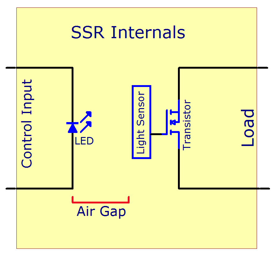
= | [[Image:SSR_Internals.png|thumb|link=|A conceptual diagram of the insides of an SSR.<br />[[Media:SSR_Internals.png|Full-size Image]]]] | ||
The control inputs are connected internally to an LED, which shines across an air gap to light sensors. The pairing of an LED with light sensors is called an optocoupler, and is a common technique to link two parts of a circuit without direct connection | The control inputs are connected internally to an LED, which shines across an air gap to light sensors. | ||
The light sensor is connected to the transistors which open or close, supplying the relay's load with power. | |||
When a transistor is '''closed''', current can flow freely through the relay, causing the load and power supply to be connected. | |||
When a transistor is '''open''', almost all current is blocked, causing the load to become disconnected from the power supply. | |||
The pairing of an LED with light sensors is called an optocoupler, and is a common technique to link two parts of a circuit without a direct electrical connection. | |||
===Basic Use=== | ===Basic Use=== | ||
Controlling an SSR is no more complicated than | Controlling an SSR is no more complicated than turning an LED on and off. Switch it on, switch it off, it is that easy (see the [[Digital Output Primer|Digital Output Primer]], or our [{{SERVER}}/products.php?product_id=1032 specific LED controller] for more). | ||
The ability of an SSR to switch a load is very similar to a relay or simple switch. | The ability of an SSR to switch a load is very similar to a [[Mechanical Relay Primer|mechanical relay]] or simple switch. | ||
By turning the digital output controlling the relay on and off, you control whether or not the load is connected to its power supply. | |||
The challenge is to pick an appropriate type of SSR for your application. There is no single SSR perfect for all applications. To choose an SSR for your particular application, please follow the [[#Choosing an SSR|Choosing an SSR]] section. | |||
<br clear=all> | |||
===Safety=== | ===Safety=== | ||
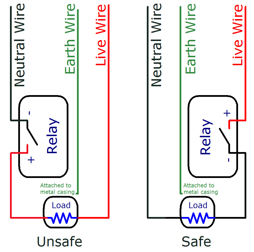
[[File:relay_safety.jpg|thumb|300px|link=|Two circuit diagrams showing the improper and proper ways of switching mains electricity with a relay.<br />[[Media:relay_safety.jpg|Full-size Image]]]] | |||
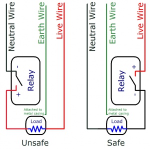
Since relays switch high currents and voltages, standard electricity safety precautions apply. Make sure you never touch the terminals while the relay is powered. If your SSR came with a plastic cover, use it. Even when the SSR is switched off, a very small amount of current will flow. | |||
When placing a relay in a circuit, it is always a good idea to put it between the power supply and the load, especially when using higher voltages. If the relay is instead placed between the load and ground, the circuit will still work the same, but when the relay is open, the load will still be directly connected to the power supply. This could cause safety concerns because someone might touch the terminals on the load, thinking it's safe because the device appears to be off. If the electricity finds a path to ground through their body, they will be electrocuted. If the relay is placed between the power supply and the ground, electrocution would only be a risk if the live terminal on the relay is touched. Again, the relay terminals should always be properly covered to avoid the risk of electrocution. | |||
When an SSR fails, it most often fails permanently closed. This is because when the transistor inside fails due to excessive current or heat, it will usually short out, allowing current to pass through unimpeded. | |||
This means that as long as the power supply remains on, the load will be powered, possibly creating a fire or safety hazard. | |||
<br clear=all> | |||
==Choosing an SSR== | |||
===Identify your voltage=== | ===Identify your voltage=== | ||
First, determine whether you need to switch AC or DC voltage. The electrical grid, and thus your wall outlet, runs AC, whereas batteries and most small power supplies are DC. | |||
Next, | Next, determine the maximum number of volts you will be switching. If you are switching DC, particularly with batteries, assume your voltage is at least 25% more than what your battery is rated for. Even larger fluctuations occur on AC, but AC SSRs are designed to handle these surges. Typical AC voltage from a wall socket in North America is 110VAC, whereas in Europe it is usually 220VAC. If you are switching AC voltage from a wall socket, check which standard your country uses, and use that number as your voltage. | ||
===Identify your current=== | ===Identify your current=== | ||
The current drawn by your load when turned on affects how large of an SSR you need, and how hot it will be when it | The current drawn by your load when turned on affects how large of an SSR you need, and how hot it will be when it is in use. If you know how much current, on average, your load draws, this is what we call '''Average Load Current'''. If you don't know the average current, but you know the wattage (power rating) of your load, you can calculate Average Load Current by: | ||
<math> | <math> | ||
\text{Average Load Current} =\frac{\text{ | \text{Average Load Current} =\frac{\text{Watts}}{\text{Operating Voltage}} | ||
</math> | </math> | ||
Next, | Next, you need to know the current drawn by your load when it is first turned on. Many loads demand a huge inrush of current when the load is first turned on. This places a significant amount of stress on the electronics inside the SSR. If you've ever noticed the lights dimming in the house for a second when the furnace starts up, this is caused by the fan motor starting up. In the same way that it takes a lot of force to move a heavy object from rest, it initially takes a lot of current to power up a fan or incandescent bulb. It's very difficult to measure the '''Surge Current''' itself, so we use a multiplier based on your device type. Surge Current is also referred to as '''inrush current'''. | ||
{| style="border:1px solid darkgray;" cellpadding="7px;" | |||
{|border= | |||
|+'''Surge Current Multiplier''' | |+'''Surge Current Multiplier''' | ||
! Application | |-style="background: #d1d1d1" align=center | ||
! Application || Multiplier | |||
|- | |- | ||
| Incandescent Light Bulbs || 6x | |style="background: #f0f0f0" align=left | Incandescent Light Bulbs | ||
|style="background: #f0f0f0" align=center| 6x | |||
|- | |- | ||
| Motors || 6x | |style="background: #f0f0f0" align=left | Motors | ||
|style="background: #f0f0f0" align=center| 6x | |||
|- | |- | ||
| LEDs || 1x | |style="background: #f0f0f0" align=left | LEDs | ||
|style="background: #f0f0f0" align=center| 1x | |||
|- | |- | ||
| Complex Electronics i.e., Motor Controllers, Phidgets || 6x | |style="background: #f0f0f0" align=left | Complex Electronics i.e., Motor Controllers, Phidgets | ||
|style="background: #f0f0f0" align=center| 6x | |||
|- | |- | ||
| Fluorescent Light Fixtures (AC Only) || 10x | |style="background: #f0f0f0" align=left | Fluorescent Light Fixtures (AC Only) | ||
|style="background: #f0f0f0" align=center| 10x | |||
|- | |- | ||
| Transformers || | |style="background: #f0f0f0" align=left | Transformers | ||
|style="background: #f0f0f0" align=center| 20x | |||
|- | |- | ||
| Heaters || | |style="background: #f0f0f0" align=left | Heaters | ||
|style="background: #f0f0f0" align=center| 1x | |||
|- | |- | ||
|} | |} | ||
| Line 91: | Line 115: | ||
Most AC applications will be switching 110 to 240 Volt power coming from the grid. If that's you, go to the [[#Mains Voltage (110 to 240V AC)|Mains Voltage (110 to 240V AC)]] section. | Most AC applications will be switching 110 to 240 Volt power coming from the grid. If that's you, go to the [[#Mains Voltage (110 to 240V AC)|Mains Voltage (110 to 240V AC)]] section. | ||
We also cover low voltage AC applications - 28 VAC or less. For more information, visit the [[#AC/DC SSRs|AC/DC SSRs]] section. | We also cover low voltage AC applications - 28 VAC (Volts AC) or less. For more information, visit the [[#AC/DC SSRs|AC/DC SSRs]] section. | ||
===I need to switch DC=== | ===I need to switch DC=== | ||
If you | If you only need to switch a small amount of current - 9 Amps or less, consider our compact, cost effective [[#AC/DC SSRs|AC/DC SSRs]]. | ||
If you need to switch more than 9 Amps, you need a serious [[#DC SSRs|DC SSR]]. | |||
If you need to switch up to 16 small loads of 2 Amps or less, you can use the open collector (externally powered) digital outputs on a [{{SERVER}}/products.php?product_id=1012 1012 PhidgetInterfaceKit 0/16/16], which can be wired to behave similarly to relays. | |||
==I need Gradual Dimming== | |||
Instead of simply turning the load on/off, if you want to dim it gradually, you can use a proportional control SSR. They are able to reduce the average power to the load gradually, in proportion to the strength of the input signal. For more information, you can visit the [[#Proportional Control SSR|Proportional Control SSR Section]]. | |||
==Mains Voltage (110 to 240V AC)== | |||
We sell AC SSRs for 120 VAC or 240 VAC operation. If you are unsure what voltages you could eventually need to switch, the 240 VAC relays can be used to switch 120 VAC with no problems. Please note we are very conservative in how we rate SSRs - our 120 VAC relays are rated by the manufacturer for 240 VAC, and the 240 VAC for 480 VAC. We strongly recommend against using them to the manufacturer rated voltage. To understand why, read the [[#AC SSR Protection|AC SSR Protection]] section. | |||
===Load Type - Inductive vs. Resistive=== | |||
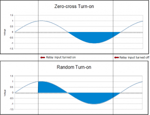
[[Image:zero cross.png|right|link=|thumb|300px|This graph shows the difference between zero-cross and random turn-on. The blue line represents the oscillating voltage of an AC load, and the shaded areas represent the sections when the relay is turned on and letting current pass through. As you can see, the random turn-on SSR immediately opens when activated, while the zero-cross turn-on SSR waits until the voltage crosses zero before opening.<br />[[Media:zero cross.png|Full-size Image]]]] | |||
If your load is inductive, you need to choose a '''Random Turn On''' relay. If your load is resistive, choose a '''Zero Crossing''' relay. | |||
Your Load will probably be inductive if it is built around a large coil of wire - motors and transformers are typical examples. A load considered resistive may also have loops of wire - for instance, hair dryers, toasters, incandescent bulbs use twisted wire elements to generate the heat. An inductive load will have thousands of loops of wire - it's a matter of scale. There is no such thing as a perfectly resistive load - but a load has to be very inductive to cause the zero crossing SSRs to malfunction. | |||
SSRs are designed to either turn on immediately ('''Random Turn On'''), or wait until the next 'alternation' of the voltage ('''Zero Crossing'''). Zero Crossing SSRs create less electromagnetic 'noise' when they turn on. They are best used with resistive loads - Zero Crossing SSRs are not able to turn off some inductive loads. It's very difficult to determine which inductive loads will create problems - well beyond the scope of this document. If your load is inductive, we recommend buying the '''Random Turn On''' SSRs. | |||
{|border= | {| style="border:1px solid darkgray;" cellpadding="7px;" | ||
|+ '''Inductive and Resistive Loads''' | |+ '''Inductive and Resistive Loads''' | ||
! Application | |-style="background: #d1d1d1" align=center | ||
! Application || Load Type | |||
|- | |- | ||
| Incandescent Light Bulbs || Resistive | |style="background: #f0f0f0" align=left| Incandescent Light Bulbs | ||
|style="background: #f0f0f0" align=left| Resistive | |||
|- | |- | ||
| Fluorescent Light Fixtures || Inductive or Resistive <font size=4>'''*'''</font> | |style="background: #f0f0f0" align=left| Fluorescent Light Fixtures | ||
|style="background: #f0f0f0" align=left| Inductive or Resistive <font size=4>'''*'''</font> | |||
|- | |- | ||
| Motors || Inductive | |style="background: #f0f0f0" align=left| Motors | ||
|style="background: #f0f0f0" align=left| Inductive | |||
|- | |- | ||
| Transformers || Inductive | |style="background: #f0f0f0" align=left| Transformers | ||
|style="background: #f0f0f0" align=left| Inductive | |||
|- | |- | ||
| Heaters || Resistive | |style="background: #f0f0f0" align=left| Heaters | ||
|style="background: #f0f0f0" align=left| Resistive | |||
|- | |- | ||
| Computer / Electronics || | |style="background: #f0f0f0" align=left| Computer / Electronics | ||
|style="background: #f0f0f0" align=left| Resistive | |||
|- | |- | ||
| AC/DC power supplies (brick heavy type) || Inductive | |style="background: #f0f0f0" align=left| AC/DC power supplies (brick heavy type) | ||
|style="background: #f0f0f0" align=left| Inductive | |||
|- | |- | ||
|AC/DC Power supplies (lightweight switchers) || Resistive | |style="background: #f0f0f0" align=left|AC/DC Power supplies (lightweight switchers) | ||
|style="background: #f0f0f0" align=left| Resistive | |||
|} | |} | ||
<font size=4>'''<nowiki>*</nowiki>'''</font> ''For fluorescent light fixtures, older units (magnetic ballast) may be inductive, and newer units are often resistive (electronic ballast).'' | <font size=4>'''<nowiki>*</nowiki>'''</font> ''For fluorescent light fixtures, older units (magnetic ballast) may be inductive, and newer units are often resistive (electronic ballast).'' | ||
===Choosing your AC SSR=== | |||
=== | |||
Now that you have identified your Operating Voltage, Average and Surge Current, and your load type (inductive or resistive), you can create a short list of relays whose | Now that you have identified your Operating Voltage, Average and Surge Current, and your load type (inductive or resistive), you can create a short list of relays whose | ||
* Maximum Load Voltage are greater than or equal to your operating voltage, | * '''Maximum Load Voltage''' are greater than or equal to your operating voltage, | ||
* Maximum Surge Current are greater than or equal to your surge current, and | * '''Maximum Surge Current''' are greater than or equal to your surge current, and | ||
* | * '''Load type''' matches what you chose for random turn on/zero crossing. | ||
Now compare the '''Load | Now compare the '''Max. Load Current without Heatsink''' value for the SSRs on your list to your Average Load Current. If your Average Load Current is greater, you may need a heatsink. For selecting a heatsink, please consult [[#Picking a heatsink|Picking a Heatsink]]. Alternatively, look at other SSRs on your list - there may be an SSR that can handle your average load current with no heatsink | ||
At this point, you know the SSR you need. | At this point, you know the SSR you need. | ||
Instead of simply turning the load on/off, | Instead of simply turning the load on/off, if you want to dim it gradually, you can use a proportional control SSR. They are able to reduce the average power to the load gradually, in proportion to the strength of the input signal. For more information, you can visit the [[#Proportional Control SSR|Proportional Control SSR Section]]. | ||
If you are interested in learning more about SSRs in general, check out our [[#Did you know?|"Did you know?"]] section. | If you are interested in learning more about SSRs in general, check out our [[#Did you know?|"Did you know?"]] section. | ||
| Line 159: | Line 192: | ||
===AC SSR Protection=== | ===AC SSR Protection=== | ||
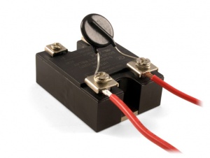
[[Image:MOV.jpg|thumb|link=|An MOV, which comes packaged with our AC "Hockey Puck" relays. ]] | |||
Your AC SSR from Phidgets comes with a circular disc with two legs (pictured). This is a Metal Oxide Varistor (MOV) and should be installed across the load (larger) terminals of your SSR. MOVs are the classic surge protector - an inexpensive component that absorbs high voltage spikes. High voltage spikes are caused by inductive loads when they are turned off, and also happen very often on the electrical grid, as nearby devices are operated. Even if your load is resistive, use an MOV to protect the SSR. | |||
Matching an MOV to an SSR is not easy - this is why we include an MOV with your SSR. If an MOV is chosen for too low of a voltage spike, it will wear out quickly. If it is chosen for too high of a voltage spike, it will not protect the SSR adequately. To balance SSR protection against MOV lifetime, we have found it necessary to use SSRs built for 240 VAC in 120 VAC applications, and SSRs built for 480 VAC in 240 VAC applications. If you must operate our AC SSRs on higher voltages than we recommend, do not use the included MOV. | |||
MOVs | As MOVs wear out from use, they will become more sensitive to common voltage spikes, causing them to wear out quicker. When they entirely fail, they will become a short circuit, potentially creating a fire hazard. The MOV included with your SSR has a fuse built in which will disable the MOV when it becomes a hazard. To be on the safe side, avoid mounting your SSR near any flammable material. | ||
For reference, the part number of the MOV shipped with our AC SSRs is '''TMOV20RP200E'''. | |||
===Proportional Control SSR=== | ===Proportional Control SSR=== | ||
Proportional Control Relays (often simply called "Control Relays") are SSRs you can use to control the amount of power to the load. Rather than reduce the voltage, or somehow limit the current - which would be very expensive solutions, the Proportional SSR reduces power by turning the load on/off quickly, feeding full power in short pulses | Proportional Control Relays (often simply called "Control Relays") are SSRs you can use to control the amount of power to the load. Rather than reduce the voltage, or somehow limit the current - which would be very expensive solutions, the Proportional SSR reduces power by turning the load on/off quickly, feeding full power in short pulses. | ||
Proportional SSRs are controlled by a variable voltage - as the voltage increases, more power is available to the load. Our PhidgetAnalog product can be used to control Proportional SSRs. We don't sell Proportional SSRs - but they can be purchased from Digikey, where they are called AC Linear Controlled SSRs. | Proportional SSRs are controlled by a variable voltage - as the control voltage increases, more power is available to the load. Our PhidgetAnalog product can be used to control Proportional SSRs, since an [[Analog Output Primer|analog output]] can output various amounts of voltage, as opposed to a digital output, which only has two states- high and low. We don't sell Proportional SSRs - but they can be purchased from [http://www.digikey.com Digikey], where they are called AC Linear Controlled SSRs. | ||
A quick and dirty | A quick and dirty solution for dimming with Phidgets is to use an {{LinksNeeded|RC Servo Motor|[[Servo Motor and Controller Primer|RC Servo Motor]]}} with a PhidgetAdvancedServo controller to rotate the knob on a light dimmer. From software, the RC Servo Motor is rotated to the desired position, cranking the knob as it turns. While this may seem like a roundabout way of achieving proportional control, dimmers tend to be much less expensive because they are less specialized and are manufactured in greater quantity. | ||
===Example circuits with AC SSRs=== | ===Example circuits with AC SSRs=== | ||
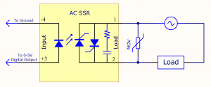
[[Image:AC SSR Load.png|right|thumb|300px|Schematic of an AC SSR switching a generic load. A metal oxide varistor is added across the load to protect the SSR.]] | [[Image:AC SSR Load.png|right|thumb|link=|300px|Schematic of an AC SSR switching a generic load. A metal oxide varistor is added across the load to protect the SSR.<br />[[Media:AC SSR Load.png|Full-size Image]]]] | ||
When wiring up an AC circuit, particularly for long term installation, you may find it helpful to buy a book on residential wiring from your local hardware store. There are many wiring conventions (and often legal codes) which will help you plan your project, and the legal codes are often a great source of wisdom. | When wiring up an AC circuit, particularly for long term installation, you may find it helpful to buy a book on residential wiring from your local hardware store. There are many wiring conventions (and often legal codes) which will help you plan your project, and the legal codes are often a great source of wisdom. | ||
| Line 190: | Line 220: | ||
==DC SSRs (0 to 50V DC)== | ==DC SSRs (0 to 50V DC)== | ||
We sell DC SSRs for | We sell DC SSRs for that switch a maximum load of 50 volts. If you are unsure what voltages you could be switching in the future, higher voltage DC SSRs can be used to switch lower voltages. Common engineering practice would be to purchase an SSR rated for 50-100% higher voltage than the voltage you plan to be switching. For instance, if you are switching 24V, a 50V SSR is reasonable. | ||
=== | ===Choosing your DC SSR=== | ||
Now that you have identified your Operating Voltage, Average and Surge Current, you can create a short list of relays whose | Now that you have identified your Operating Voltage, Average and Surge Current, you can create a short list of relays whose | ||
* Maximum Load Voltage are greater than or equal to your operating voltage, | * Maximum Load Voltage are greater than or equal to your operating voltage, | ||
* Maximum Surge Current are greater than or equal to your surge current, and | * Maximum Surge Current are greater than or equal to your surge current, and | ||
* Maximum Average Current is greater than or equal to your Average current. | |||
Now compare the '''Load | Now compare the '''Max. Load Current without Heatsink''' value for the SSRs on your list to your Average Load Current. If your Average Load Current is greater, you may need a heatsink. For selecting a heatsink, please consult [[#Picking a Heatsink|Picking a Heatsink]]. Alternatively, look at other SSRs on your list - there may be an SSR that can handle your average load current without a heatsink. SSRs rated for a larger load than the load you're using will be more efficient (meaning less energy lost in the form of heat) than an SSR that's being operated at its maximum load. | ||
At this point, you know the SSR you need. | At this point, you know the SSR you need. | ||
| Line 206: | Line 237: | ||
===DC SSR Protection=== | ===DC SSR Protection=== | ||
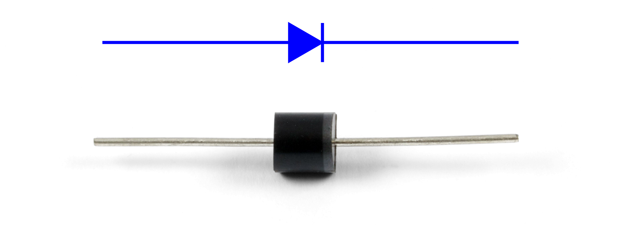
[[Image:Diode.jpg|thumb| A diode, included with our DC "hockey puck" SSRs. The cathode is marked with a line. The blue symbol shows circuit diagram equivalent of the diode.]] | [[Image:Diode.jpg|thumb|300px|link=| A diode, included with our DC "hockey puck" SSRs. The cathode is marked with a line. The blue symbol shows circuit diagram equivalent of the diode.<br>[[Media:Diode.jpg|Full-Sized Image]]]] | ||
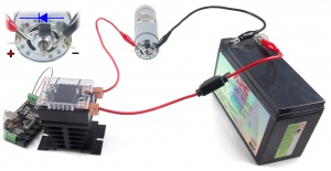
[[Image:relaymotor.jpg|thumb| A DC SSR switching an electric motor. The 1018 Phidget InterfaceKit controls the SSR using its digital outputs. A diode is shown installed across the motor, and a fuse is hooked up between the power supply and the rest of the circuit.]] | [[Image:relaymotor.jpg|300px|thumb|link=| A DC SSR switching an electric motor. The 1018 Phidget InterfaceKit controls the SSR using its digital outputs. A diode is shown installed across the motor, and a fuse is hooked up between the power supply and the rest of the circuit.<br>[[Media:relaymotor.jpg|Full-Sized Image]]]] | ||
Your DC SSR from Phidgets comes with a diode. This diode should be installed across your load, with the Cathode installed towards the power supply. | Your DC SSR from Phidgets comes with a diode. This diode should be installed across your load, with the Cathode installed towards the positive terminal of the power supply (as shown in the diagram). | ||
If the diode is installed backwards, as soon as the SSR is turned on, the load will be shorted out, likely destroying the diode, or the SSR, or your power supply. | If the diode is installed backwards, as soon as the SSR is turned on, the load will be shorted out, likely destroying the diode, or the SSR, or your power supply. | ||
A fuse protecting your power supply is always a good idea. | A fuse protecting your power supply is always a good idea. You can place the fuse in between the positive terminal of the power supply and the positive terminal of the load side of the SSR. | ||
The diode protects the SSR from powerful residual currents after the SSR is turned off. | The diode protects the SSR from powerful residual currents after the SSR is turned off. While your load is being driven, inductance builds up magnetic fields around the wiring. | ||
Every load is inductive to some degree, and when the SSR turns off, the magnetic fields will ram current against the now open SSR, easily damaging it. The diode allows these currents to recirculate in the load until they have lost their energy. | |||
For reference, the part number of the diode that comes with our DC SSRs is '''10A02-T'''. | |||
<br clear="all"> | <br clear="all"> | ||
| Line 221: | Line 255: | ||
===Example circuits with DC SSRs=== | ===Example circuits with DC SSRs=== | ||
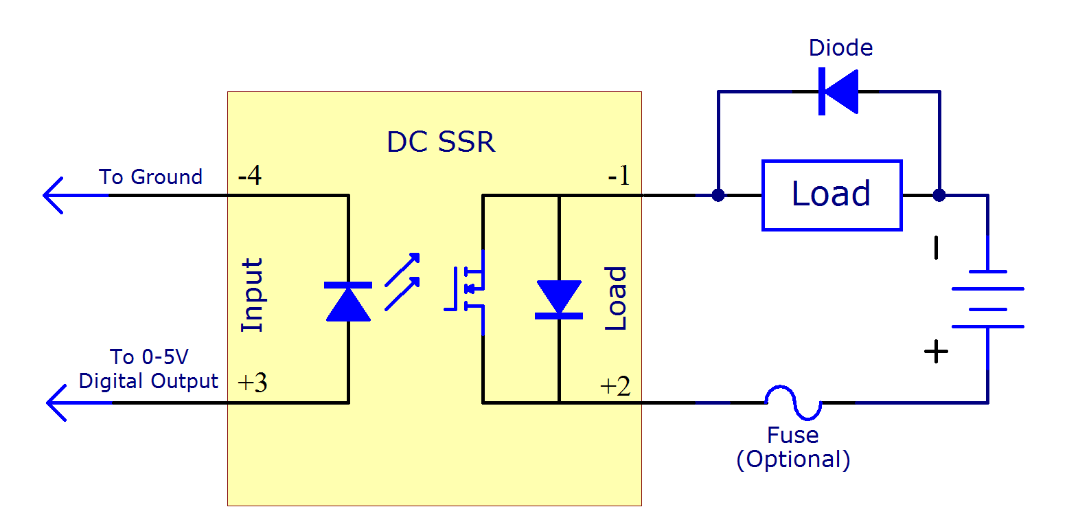
[[Image:DC SSR Load.png|right|thumb|300px|Schematic of an DC SSR switching a generic load, which is protected by a diode connected in parallel. The circuit is protected by a fuse in series after the power supply.]] | [[Image:DC SSR Load.png|right|link=|thumb|300px|Schematic of an DC SSR switching a generic load, which is protected by a diode connected in parallel. The circuit is protected by a fuse in series after the power supply.<br />[[Media:DC SSR Load.png|Full-size Image]]]] | ||
The electrical isolation built into a DC SSR allows them to be placed within a circuit just like a switch. | The electrical isolation built into a DC SSR allows them to be placed within a circuit just like a switch. Since it is isolated, you don't have to worry about grounding or voltage offsets. | ||
With a DC SSR, always make sure the positive load terminal (labeled +) is facing towards the positive terminal of the power supply. If the load terminals are reversed, your load will immediately turn on | With a DC SSR, always make sure the positive load terminal (labeled +) is facing towards the positive terminal of the power supply. If the load terminals are reversed, your load will immediately turn on. There is a diode inside of the SSR that allows current to flow freely through it when the SSR is connected incorrectly. This feature is included because this sort of wiring mistake would destroy the transistor in the DC SSR otherwise. | ||
The DC SSR can be installed on either side of the load, and it will work properly, but there is an advantage to installing the SSR between the power supply and the load. If the load is connected to the power supply, it will always have a potentially dangerous voltage on it, even when it is not operating. | The DC SSR can be installed on either side of the load, and it will work properly, but there is an advantage to installing the SSR between the power supply and the load. If the load is connected to the power supply, it will always have a potentially dangerous voltage on it, even when it is not operating. | ||
| Line 234: | Line 268: | ||
==AC/DC SSRs (0 to 40V DC / 0 to 28V AC)== | ==AC/DC SSRs (0 to 40V DC / 0 to 28V AC)== | ||
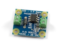
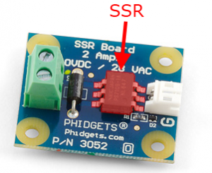
[[Image:AC_DC_SSR.png|thumb|link=|A small, versatile AC/DC SSR mounted on a Phidgets board for easy pin access.]] | |||
We sell AC/DC SSRs that can switch up to 40 Volts DC or 28 Volts AC. | Our AC/DC SSRs are built on a small PCB, making them physically smaller than the large "hockey puck" SSRs, and less expensive. They are limited to lower currents, and cannot be mounted on a heatsink. | ||
We sell AC/DC SSRs that can switch up to 40 Volts DC or 28 Volts AC. This is indicated on the SSR Product pages under the Maximum Load Voltage specification. There is no lower limit on the voltages that the AC/DC SSRs can switch. If your voltage is close - be conservative. For instance, a 36 Volt system built from 3 Lead Acid batteries can reach 45 volts when charging. | |||
===Picking your AC/DC SSR=== | ===Picking your AC/DC SSR=== | ||
| Line 247: | Line 283: | ||
If you are interested in minimum cost, you will likely choose the cheapest option that meets these criteria. If you are interested in high efficiency operation and less heat generation, consider buying an SSR with higher current rating. | If you are interested in minimum cost, you will likely choose the cheapest option that meets these criteria. If you are interested in high efficiency operation and less heat generation, consider buying an SSR with higher current rating. | ||
Your AC/DC SSR from Phidgets has built in protection from static electricity, and dangerous residual currents after the SSR is turned off. If you are switching DC, installing a diode across the load will offer even more protection. Refer to the [[#DC SSR Protection|DC SSR Protection]] section for more information. | Your AC/DC SSR from Phidgets has built in protection from static electricity, and dangerous residual currents after the SSR is turned off. If the load you are switching is powered by a DC source, installing a diode across the load will offer even more protection. Refer to the [[#DC SSR Protection|DC SSR Protection]] section for more information. | ||
To learn more about SSRs in general, visit the [[#Did you know?|"Did you know?"]] section. | |||
<br clear="all"> | |||
===Example circuits with AC/DC SSRs=== | ===Example circuits with AC/DC SSRs=== | ||
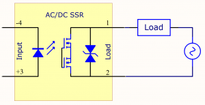
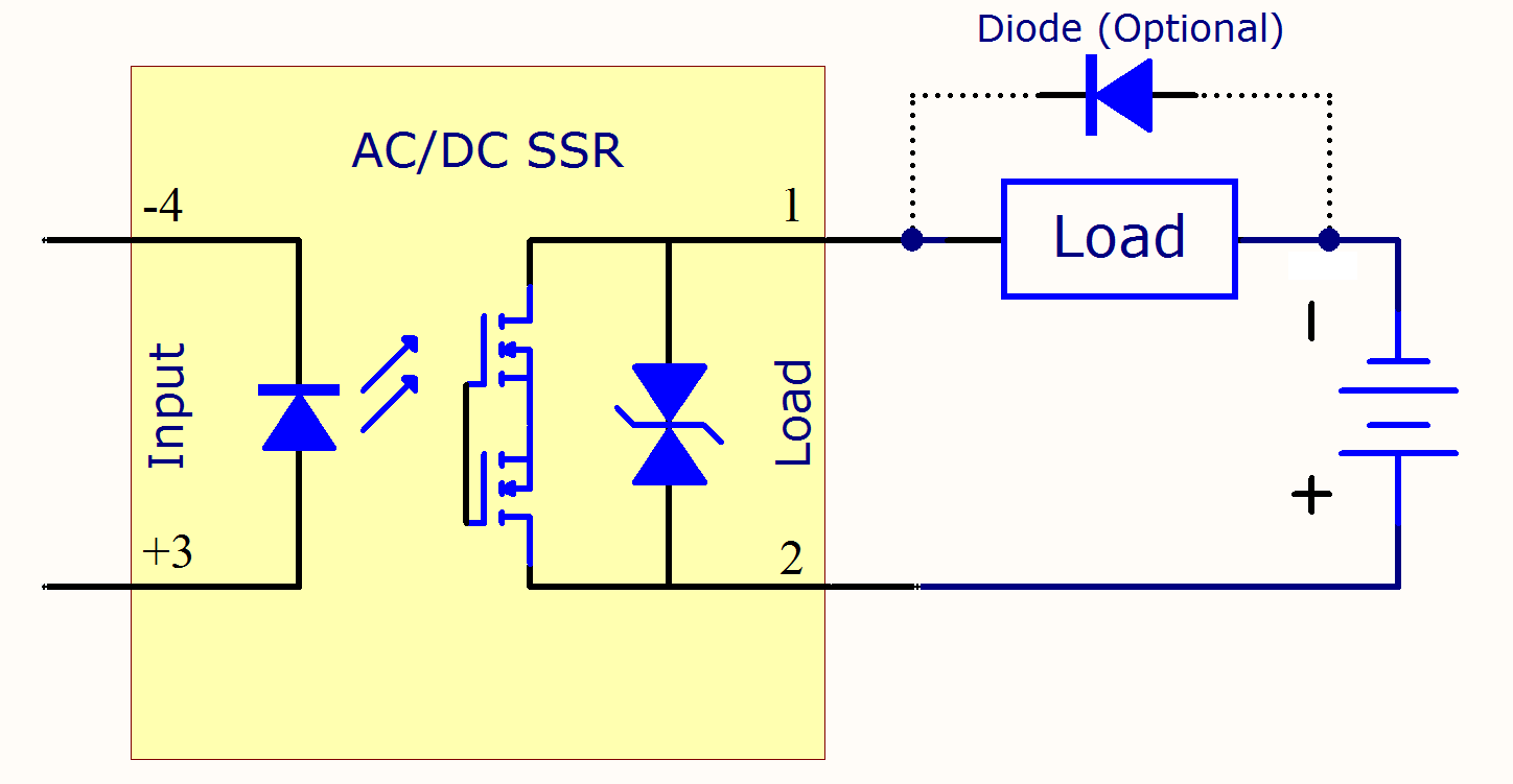
[[Image:Versatile SSR DC Load.png|thumb|link=|A versatile AC/DC SSR switching a DC load. The load terminals are bidirectional, so it doesn't matter which way you hook them up. The optional diode can be added to help protect the SSR when switching DC loads.<br />[[Media:Versatile SSR DC Load.png|Full-size Image]]]] | |||
[[Image:Versatile SSR AC Load.png|thumb|link=|A versatile AC/DC SSR switching an AC load.<br />[[Media:Versatile SSR AC Load.png|Full-size Image]]]] | |||
The electrical isolation built into a AC/DC SSR allows them to be placed within a circuit just like a switch. Circuits without electrical isolation require a lot more care - proper grounding, careful consideration of voltage offsets. | |||
<br clear="all"> | |||
==Using heatsinks with Hockey Puck SSRs== | ==Using heatsinks with Hockey Puck SSRs== | ||
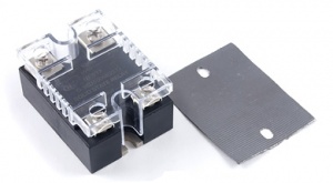
[[Image:3950_0 Accessories Web.jpg|thumb|link=|A "hockey puck" SSR with plastic cover (left), a thermal pad (right). All hockey puck SSRs sold at Phidgets come with both of these accessories plus a diode or varistor to protect the SSR.]] | |||
[[Image:3955_0 Functional Web.jpg|thumb|link=|A "hockey puck" SSR mounted on a small heatsink by two screws. The thermal pad is pressed between the SSR and the heatsink.]] | |||
SSRs will only achieve their promise of reliability and long life if they are kept cool. Cool is relative, of course, but a good rule of thumb is to keep the metal base of the SSR at less than 85°C (185°F). A [[Thermocouple Primer|thermocouple]] can be used to precisely measure the temperature of the metal base. | |||
Excess heat usually comes from too much current and too little heatsinking. A lot of heat can also be generated by frequently turning the relay on and off. If your relay is operated for brief periods of time, you may not need as large of a heatsink - provided the relay is never accidentally left on for extended periods. Unless space is a concern, it's better to err on the side of caution. | |||
Each SSR suitable for use with heatsinks will include a specification of how much current it can switch with each heatsink we sell. This specification assumes a reasonable airflow over the heatsink, and that the flowing air is at room temperature. Our SSRs have a sheet of metal underneath, where the heat is concentrated - this is also where the heat is measured to tell if the SSR is too hot. Phidgets includes a | Before buying a heatsink, consider if you actually need it. If your application is running at room temperature, and your average current is less than the '''Max. Load Current without Heatsink''' specification of your SSR, then you don't need a heatsink. Alternatively, if your project has a large metal chassis that the SSR can bolt to, this can be used as your heatsink. | ||
Each SSR suitable for use with heatsinks will include a specification of how much current it can switch with each heatsink we sell. This specification assumes a reasonable airflow over the heatsink, and that the flowing air is at room temperature. Our SSRs have a sheet of metal underneath, where the heat is concentrated - this is also where the heat is measured to tell if the SSR is too hot. Phidgets includes a thermal pad with our Hockey Puck SSRs (see pictured). You place this pad under an SSR when mounting it on a heatsink, or on large metal surfaces that can dissipate heat. The pad performs the same function as thermal grease - it helps conduct heat between the base of the SSR and the heatsink. If you prefer to use thermal grease, you can use it instead of the pad. Our heatsinks include screws for mounting SSRs. Use a good size screwdriver when tightening the SSR down on the heatsink to ensure good conduction. | |||
You can see our selection of heatsinks in the [http://www.phidgets.com/products.php?category=9 relays] category of our store. | |||
<br clear="all"> | |||
==Hooking up wires to the Hockey Puck SSR== | ==Hooking up wires to the Hockey Puck SSR== | ||
[[Image:relay_mov.jpg|thumb|link=|An AC SSR with the wires attached normally and an MOV installed across the load side.]] | |||
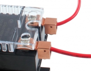
[[Image:lugs.jpg|thumb|link=|TRM6 wiring lugs connected to a DC SSR.]] | |||
When wiring your load to the SSR, the wire is looped clockwise around the terminal, so | When wiring your load to the SSR, the wire is looped clockwise around the terminal, so when the screw is tightened down, it will draw the wire in tighter. We recommend using wires up to 10 AWG in size - any larger, and the screws will not have enough thread left to tighten down, and they will strip. Larger wires can be attached using a wiring lug. The lug is clamped under the SSR screw, and the wire attaches to the lug. | ||
Loose wire connections can generate a lot of heat - use a | Loose wire connections can generate a lot of heat - use a large enough screwdriver when clamping down the load wires to ensure that the screws are on tight enough. | ||
For the current ratings of various wires sizes, please see [[Page on Wire Sizes]] | For the current ratings of various wires sizes, please see [[Electricity_Primer#Cable_Gauges_for_Terminal_Blocks|Page on Wire Sizes]]. | ||
= | <br clear="all"> | ||
==Did you know?== | |||
* Mains Voltage '''AC SSRs''' cannot switch DC. They will never turn the load off. AC SSRs turn off twice per AC Cycle, when the current changes direction and is momentarily zero. For example, AC is 60 Hz in North America, so the AC SSR has 120 opportunities per second to turn off (the SSR will only '''stay''' off if the control signal is low). If the SSR is operating from DC, the current will flow continuously, and the load will not turn off, even when the control input is off. | |||
* An '''AC SSR''' turns off automatically every time the load current reaches zero. It will turn back on almost immediately as long as the signal controlling the SSR is high. An AC SSR will actually have a low, non-zero current value that it regards as 'zero'. This specification is usually called "Minimum Load Current" in the data sheet. If your load requires less than this minimum current, your SSR will never turn on, or will not reliably turn on. The simplest solution to this problem is to connect another load in parallel with the first, increasing the Current required by the load. | |||
* SSR Manufacturers have started adding a simple circuit inside '''AC SSRs''', across the load terminals, called a snubber. The snubber absorbs very fast electrical changes that could normally cause an '''AC SSR''' to turn on accidentally. When the AC SSR is turned on, there is little voltage difference between the terminals, so the snubber has very little effect. When the AC SSR is turned off, the snubber is actively protecting the SSR - but at a cost, as it allows a small current through the SSR, which is wasted. | |||
* An '''AC SSR''' uses bipolar transistors - an old technology that has been replaced by CMOS transistors in modern digital circuits. Bipolar transistors are still superior for handling high voltages. Bipolar transistors, and the more complex transistors built from them, will lose a constant voltage as current flows through them. The collection of transistors in your SSR will lose about 1.7 volts - so on a 120 VAC system, you will lose about 1.5% to the SSR. This energy converts to heat inside the SSR, and the heating from these transistors is the reason SSRs often need heatsinks. | |||
* SSRs, and semiconductors in general, usually fail as a short circuit. A short circuit is a circuit whose internals have been damaged such that current can flow through it freely. This means your load will probably turn on permanently (until you disconnect the power source) - make sure this doesn't cause a safety hazard. For instance, Sauna Heaters have a simple thermally-triggered mechanical shutdown to protect them if control electronics fails. | |||
MOSFETs | * '''DC SSRs''' (at least the units we sell) use Metal Oxide Semiconductor Field Effect Transistors (MOSFETs). MOSFETs do not lose a constant voltage - instead, when they turn on, they act as a very slight restriction to the flow of current - a resistor. At low currents, the slight restriction wastes very little power, giving high efficiency and often not requiring a heatsink. This efficiency is lost as the current increases - a doubling of current quadruples the production of heat. | ||
* Normally, a MOSFET can only block current in one direction - as soon as the voltage reverses, the current flows through a diode run in parallel to the MOSFET. If a MOSFET were used to switch AC, the load would be turned on half the time. A common solution is to use two MOSFETs back to back - which is what we do with our '''AC/DC SSRs'''. | |||
Latest revision as of 17:00, 7 June 2017
|
|
Introduction
Solid state relays (SSRs) turn on or off the power being supplied to other devices, in a similar fashion as a physical switch. However, instead of being switched by human interaction like a physical switch, SSRs are switched electronically. With SSRs, you can control high-current devices such as lights or appliances with low-current signals, like a standard DC signal from a Digital Output. Most SSRs will switch on with a voltage of 3V or higher. This makes them perfect for use with Phidget Interface Kits, or any device with a digital output.
SSRs perform the same job as Mechanical Relays, but have the following advantages:
- SSRs produce less electromagnetic interference than mechanical relays during operation. This is mostly due to the absence of a phenomenon called contact arcing only present in mechanical relays, where the physical contacts of the relay tend to spark internally while switching. The reduced interference can also be attributed to the fact that SSRs do not use electromagnets to switch.
- The switch contacts of a mechanical relay will eventually wear down from arcing. An SSR will have a longer life because its internals are purely digital. Properly used, they will last for millions of cycles.
- SSRs turn on and off faster than mechanical relays (≈1ms compared to ≈10ms).
- SSRs are less susceptible to physical vibrations than mechanical relays.
- Since the switch inside an SSR isn't a mechanical switch, it does not suffer from contact bounce and operates silently.
However, compared to Mechanical Relays, SSRs:
- Are more expensive.
- Will dissipate more energy in the form of heat (1-2% of the energy intended to power the load).
How SSRs Work

The control inputs are connected internally to an LED, which shines across an air gap to light sensors. The light sensor is connected to the transistors which open or close, supplying the relay's load with power. When a transistor is closed, current can flow freely through the relay, causing the load and power supply to be connected. When a transistor is open, almost all current is blocked, causing the load to become disconnected from the power supply. The pairing of an LED with light sensors is called an optocoupler, and is a common technique to link two parts of a circuit without a direct electrical connection.
Basic Use
Controlling an SSR is no more complicated than turning an LED on and off. Switch it on, switch it off, it is that easy (see the Digital Output Primer, or our specific LED controller for more).
The ability of an SSR to switch a load is very similar to a mechanical relay or simple switch. By turning the digital output controlling the relay on and off, you control whether or not the load is connected to its power supply.
The challenge is to pick an appropriate type of SSR for your application. There is no single SSR perfect for all applications. To choose an SSR for your particular application, please follow the Choosing an SSR section.
Safety
Full-size Image
Since relays switch high currents and voltages, standard electricity safety precautions apply. Make sure you never touch the terminals while the relay is powered. If your SSR came with a plastic cover, use it. Even when the SSR is switched off, a very small amount of current will flow.
When placing a relay in a circuit, it is always a good idea to put it between the power supply and the load, especially when using higher voltages. If the relay is instead placed between the load and ground, the circuit will still work the same, but when the relay is open, the load will still be directly connected to the power supply. This could cause safety concerns because someone might touch the terminals on the load, thinking it's safe because the device appears to be off. If the electricity finds a path to ground through their body, they will be electrocuted. If the relay is placed between the power supply and the ground, electrocution would only be a risk if the live terminal on the relay is touched. Again, the relay terminals should always be properly covered to avoid the risk of electrocution.
When an SSR fails, it most often fails permanently closed. This is because when the transistor inside fails due to excessive current or heat, it will usually short out, allowing current to pass through unimpeded. This means that as long as the power supply remains on, the load will be powered, possibly creating a fire or safety hazard.
Choosing an SSR
Identify your voltage
First, determine whether you need to switch AC or DC voltage. The electrical grid, and thus your wall outlet, runs AC, whereas batteries and most small power supplies are DC.
Next, determine the maximum number of volts you will be switching. If you are switching DC, particularly with batteries, assume your voltage is at least 25% more than what your battery is rated for. Even larger fluctuations occur on AC, but AC SSRs are designed to handle these surges. Typical AC voltage from a wall socket in North America is 110VAC, whereas in Europe it is usually 220VAC. If you are switching AC voltage from a wall socket, check which standard your country uses, and use that number as your voltage.
Identify your current
The current drawn by your load when turned on affects how large of an SSR you need, and how hot it will be when it is in use. If you know how much current, on average, your load draws, this is what we call Average Load Current. If you don't know the average current, but you know the wattage (power rating) of your load, you can calculate Average Load Current by:

Next, you need to know the current drawn by your load when it is first turned on. Many loads demand a huge inrush of current when the load is first turned on. This places a significant amount of stress on the electronics inside the SSR. If you've ever noticed the lights dimming in the house for a second when the furnace starts up, this is caused by the fan motor starting up. In the same way that it takes a lot of force to move a heavy object from rest, it initially takes a lot of current to power up a fan or incandescent bulb. It's very difficult to measure the Surge Current itself, so we use a multiplier based on your device type. Surge Current is also referred to as inrush current.
| Application | Multiplier |
|---|---|
| Incandescent Light Bulbs | 6x |
| Motors | 6x |
| LEDs | 1x |
| Complex Electronics i.e., Motor Controllers, Phidgets | 6x |
| Fluorescent Light Fixtures (AC Only) | 10x |
| Transformers | 20x |
| Heaters | 1x |
Multiply your Average Load Current by the multiplier for your device type to calculate the Surge Current.
I need to switch AC
Most AC applications will be switching 110 to 240 Volt power coming from the grid. If that's you, go to the Mains Voltage (110 to 240V AC) section.
We also cover low voltage AC applications - 28 VAC (Volts AC) or less. For more information, visit the AC/DC SSRs section.
I need to switch DC
If you only need to switch a small amount of current - 9 Amps or less, consider our compact, cost effective AC/DC SSRs.
If you need to switch more than 9 Amps, you need a serious DC SSR.
If you need to switch up to 16 small loads of 2 Amps or less, you can use the open collector (externally powered) digital outputs on a 1012 PhidgetInterfaceKit 0/16/16, which can be wired to behave similarly to relays.
I need Gradual Dimming
Instead of simply turning the load on/off, if you want to dim it gradually, you can use a proportional control SSR. They are able to reduce the average power to the load gradually, in proportion to the strength of the input signal. For more information, you can visit the Proportional Control SSR Section.
Mains Voltage (110 to 240V AC)
We sell AC SSRs for 120 VAC or 240 VAC operation. If you are unsure what voltages you could eventually need to switch, the 240 VAC relays can be used to switch 120 VAC with no problems. Please note we are very conservative in how we rate SSRs - our 120 VAC relays are rated by the manufacturer for 240 VAC, and the 240 VAC for 480 VAC. We strongly recommend against using them to the manufacturer rated voltage. To understand why, read the AC SSR Protection section.
Load Type - Inductive vs. Resistive
Full-size Image
If your load is inductive, you need to choose a Random Turn On relay. If your load is resistive, choose a Zero Crossing relay.
Your Load will probably be inductive if it is built around a large coil of wire - motors and transformers are typical examples. A load considered resistive may also have loops of wire - for instance, hair dryers, toasters, incandescent bulbs use twisted wire elements to generate the heat. An inductive load will have thousands of loops of wire - it's a matter of scale. There is no such thing as a perfectly resistive load - but a load has to be very inductive to cause the zero crossing SSRs to malfunction.
SSRs are designed to either turn on immediately (Random Turn On), or wait until the next 'alternation' of the voltage (Zero Crossing). Zero Crossing SSRs create less electromagnetic 'noise' when they turn on. They are best used with resistive loads - Zero Crossing SSRs are not able to turn off some inductive loads. It's very difficult to determine which inductive loads will create problems - well beyond the scope of this document. If your load is inductive, we recommend buying the Random Turn On SSRs.
| Application | Load Type |
|---|---|
| Incandescent Light Bulbs | Resistive |
| Fluorescent Light Fixtures | Inductive or Resistive * |
| Motors | Inductive |
| Transformers | Inductive |
| Heaters | Resistive |
| Computer / Electronics | Resistive |
| AC/DC power supplies (brick heavy type) | Inductive |
| AC/DC Power supplies (lightweight switchers) | Resistive |
* For fluorescent light fixtures, older units (magnetic ballast) may be inductive, and newer units are often resistive (electronic ballast).
Choosing your AC SSR
Now that you have identified your Operating Voltage, Average and Surge Current, and your load type (inductive or resistive), you can create a short list of relays whose
- Maximum Load Voltage are greater than or equal to your operating voltage,
- Maximum Surge Current are greater than or equal to your surge current, and
- Load type matches what you chose for random turn on/zero crossing.
Now compare the Max. Load Current without Heatsink value for the SSRs on your list to your Average Load Current. If your Average Load Current is greater, you may need a heatsink. For selecting a heatsink, please consult Picking a Heatsink. Alternatively, look at other SSRs on your list - there may be an SSR that can handle your average load current with no heatsink
At this point, you know the SSR you need.
Instead of simply turning the load on/off, if you want to dim it gradually, you can use a proportional control SSR. They are able to reduce the average power to the load gradually, in proportion to the strength of the input signal. For more information, you can visit the Proportional Control SSR Section.
If you are interested in learning more about SSRs in general, check out our "Did you know?" section.
AC SSR Protection
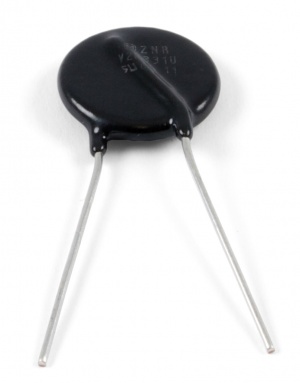
Your AC SSR from Phidgets comes with a circular disc with two legs (pictured). This is a Metal Oxide Varistor (MOV) and should be installed across the load (larger) terminals of your SSR. MOVs are the classic surge protector - an inexpensive component that absorbs high voltage spikes. High voltage spikes are caused by inductive loads when they are turned off, and also happen very often on the electrical grid, as nearby devices are operated. Even if your load is resistive, use an MOV to protect the SSR.
Matching an MOV to an SSR is not easy - this is why we include an MOV with your SSR. If an MOV is chosen for too low of a voltage spike, it will wear out quickly. If it is chosen for too high of a voltage spike, it will not protect the SSR adequately. To balance SSR protection against MOV lifetime, we have found it necessary to use SSRs built for 240 VAC in 120 VAC applications, and SSRs built for 480 VAC in 240 VAC applications. If you must operate our AC SSRs on higher voltages than we recommend, do not use the included MOV.
As MOVs wear out from use, they will become more sensitive to common voltage spikes, causing them to wear out quicker. When they entirely fail, they will become a short circuit, potentially creating a fire hazard. The MOV included with your SSR has a fuse built in which will disable the MOV when it becomes a hazard. To be on the safe side, avoid mounting your SSR near any flammable material.
For reference, the part number of the MOV shipped with our AC SSRs is TMOV20RP200E.
Proportional Control SSR
Proportional Control Relays (often simply called "Control Relays") are SSRs you can use to control the amount of power to the load. Rather than reduce the voltage, or somehow limit the current - which would be very expensive solutions, the Proportional SSR reduces power by turning the load on/off quickly, feeding full power in short pulses.
Proportional SSRs are controlled by a variable voltage - as the control voltage increases, more power is available to the load. Our PhidgetAnalog product can be used to control Proportional SSRs, since an analog output can output various amounts of voltage, as opposed to a digital output, which only has two states- high and low. We don't sell Proportional SSRs - but they can be purchased from Digikey, where they are called AC Linear Controlled SSRs.
A quick and dirty solution for dimming with Phidgets is to use an RC Servo Motor with a PhidgetAdvancedServo controller to rotate the knob on a light dimmer. From software, the RC Servo Motor is rotated to the desired position, cranking the knob as it turns. While this may seem like a roundabout way of achieving proportional control, dimmers tend to be much less expensive because they are less specialized and are manufactured in greater quantity.
Example circuits with AC SSRs
Full-size Image
When wiring up an AC circuit, particularly for long term installation, you may find it helpful to buy a book on residential wiring from your local hardware store. There are many wiring conventions (and often legal codes) which will help you plan your project, and the legal codes are often a great source of wisdom.
DC SSRs (0 to 50V DC)
We sell DC SSRs for that switch a maximum load of 50 volts. If you are unsure what voltages you could be switching in the future, higher voltage DC SSRs can be used to switch lower voltages. Common engineering practice would be to purchase an SSR rated for 50-100% higher voltage than the voltage you plan to be switching. For instance, if you are switching 24V, a 50V SSR is reasonable.
Choosing your DC SSR
Now that you have identified your Operating Voltage, Average and Surge Current, you can create a short list of relays whose
- Maximum Load Voltage are greater than or equal to your operating voltage,
- Maximum Surge Current are greater than or equal to your surge current, and
- Maximum Average Current is greater than or equal to your Average current.
Now compare the Max. Load Current without Heatsink value for the SSRs on your list to your Average Load Current. If your Average Load Current is greater, you may need a heatsink. For selecting a heatsink, please consult Picking a Heatsink. Alternatively, look at other SSRs on your list - there may be an SSR that can handle your average load current without a heatsink. SSRs rated for a larger load than the load you're using will be more efficient (meaning less energy lost in the form of heat) than an SSR that's being operated at its maximum load.
At this point, you know the SSR you need.
If you are interested in learning more about SSRs in general, check out our "Did you know?" section.
DC SSR Protection
Full-Sized Image
Full-Sized Image
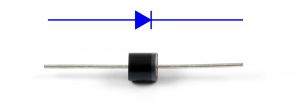
Your DC SSR from Phidgets comes with a diode. This diode should be installed across your load, with the Cathode installed towards the positive terminal of the power supply (as shown in the diagram).
If the diode is installed backwards, as soon as the SSR is turned on, the load will be shorted out, likely destroying the diode, or the SSR, or your power supply. A fuse protecting your power supply is always a good idea. You can place the fuse in between the positive terminal of the power supply and the positive terminal of the load side of the SSR.
The diode protects the SSR from powerful residual currents after the SSR is turned off. While your load is being driven, inductance builds up magnetic fields around the wiring. Every load is inductive to some degree, and when the SSR turns off, the magnetic fields will ram current against the now open SSR, easily damaging it. The diode allows these currents to recirculate in the load until they have lost their energy.
For reference, the part number of the diode that comes with our DC SSRs is 10A02-T.
Example circuits with DC SSRs
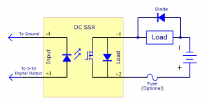
Full-size Image
The electrical isolation built into a DC SSR allows them to be placed within a circuit just like a switch. Since it is isolated, you don't have to worry about grounding or voltage offsets.
With a DC SSR, always make sure the positive load terminal (labeled +) is facing towards the positive terminal of the power supply. If the load terminals are reversed, your load will immediately turn on. There is a diode inside of the SSR that allows current to flow freely through it when the SSR is connected incorrectly. This feature is included because this sort of wiring mistake would destroy the transistor in the DC SSR otherwise.
The DC SSR can be installed on either side of the load, and it will work properly, but there is an advantage to installing the SSR between the power supply and the load. If the load is connected to the power supply, it will always have a potentially dangerous voltage on it, even when it is not operating.
AC/DC SSRs (0 to 40V DC / 0 to 28V AC)
Our AC/DC SSRs are built on a small PCB, making them physically smaller than the large "hockey puck" SSRs, and less expensive. They are limited to lower currents, and cannot be mounted on a heatsink.
We sell AC/DC SSRs that can switch up to 40 Volts DC or 28 Volts AC. This is indicated on the SSR Product pages under the Maximum Load Voltage specification. There is no lower limit on the voltages that the AC/DC SSRs can switch. If your voltage is close - be conservative. For instance, a 36 Volt system built from 3 Lead Acid batteries can reach 45 volts when charging.
Picking your AC/DC SSR
Now that you have identified your Operating Voltage, Average and Surge Current, you can create a short list of relays whose
- Maximum Load Voltage are greater than or equal to your operating voltage,
- Maximum Surge Current are greater than or equal to your surge current, and
- Maximum Average Current is greater than or equal to your Average current.
If you are interested in minimum cost, you will likely choose the cheapest option that meets these criteria. If you are interested in high efficiency operation and less heat generation, consider buying an SSR with higher current rating.
Your AC/DC SSR from Phidgets has built in protection from static electricity, and dangerous residual currents after the SSR is turned off. If the load you are switching is powered by a DC source, installing a diode across the load will offer even more protection. Refer to the DC SSR Protection section for more information.
To learn more about SSRs in general, visit the "Did you know?" section.
Example circuits with AC/DC SSRs

Full-size Image
The electrical isolation built into a AC/DC SSR allows them to be placed within a circuit just like a switch. Circuits without electrical isolation require a lot more care - proper grounding, careful consideration of voltage offsets.
Using heatsinks with Hockey Puck SSRs
SSRs will only achieve their promise of reliability and long life if they are kept cool. Cool is relative, of course, but a good rule of thumb is to keep the metal base of the SSR at less than 85°C (185°F). A thermocouple can be used to precisely measure the temperature of the metal base.
Excess heat usually comes from too much current and too little heatsinking. A lot of heat can also be generated by frequently turning the relay on and off. If your relay is operated for brief periods of time, you may not need as large of a heatsink - provided the relay is never accidentally left on for extended periods. Unless space is a concern, it's better to err on the side of caution.
Before buying a heatsink, consider if you actually need it. If your application is running at room temperature, and your average current is less than the Max. Load Current without Heatsink specification of your SSR, then you don't need a heatsink. Alternatively, if your project has a large metal chassis that the SSR can bolt to, this can be used as your heatsink.
Each SSR suitable for use with heatsinks will include a specification of how much current it can switch with each heatsink we sell. This specification assumes a reasonable airflow over the heatsink, and that the flowing air is at room temperature. Our SSRs have a sheet of metal underneath, where the heat is concentrated - this is also where the heat is measured to tell if the SSR is too hot. Phidgets includes a thermal pad with our Hockey Puck SSRs (see pictured). You place this pad under an SSR when mounting it on a heatsink, or on large metal surfaces that can dissipate heat. The pad performs the same function as thermal grease - it helps conduct heat between the base of the SSR and the heatsink. If you prefer to use thermal grease, you can use it instead of the pad. Our heatsinks include screws for mounting SSRs. Use a good size screwdriver when tightening the SSR down on the heatsink to ensure good conduction.
You can see our selection of heatsinks in the relays category of our store.
Hooking up wires to the Hockey Puck SSR
When wiring your load to the SSR, the wire is looped clockwise around the terminal, so when the screw is tightened down, it will draw the wire in tighter. We recommend using wires up to 10 AWG in size - any larger, and the screws will not have enough thread left to tighten down, and they will strip. Larger wires can be attached using a wiring lug. The lug is clamped under the SSR screw, and the wire attaches to the lug.
Loose wire connections can generate a lot of heat - use a large enough screwdriver when clamping down the load wires to ensure that the screws are on tight enough.
For the current ratings of various wires sizes, please see Page on Wire Sizes.
Did you know?
- Mains Voltage AC SSRs cannot switch DC. They will never turn the load off. AC SSRs turn off twice per AC Cycle, when the current changes direction and is momentarily zero. For example, AC is 60 Hz in North America, so the AC SSR has 120 opportunities per second to turn off (the SSR will only stay off if the control signal is low). If the SSR is operating from DC, the current will flow continuously, and the load will not turn off, even when the control input is off.
- An AC SSR turns off automatically every time the load current reaches zero. It will turn back on almost immediately as long as the signal controlling the SSR is high. An AC SSR will actually have a low, non-zero current value that it regards as 'zero'. This specification is usually called "Minimum Load Current" in the data sheet. If your load requires less than this minimum current, your SSR will never turn on, or will not reliably turn on. The simplest solution to this problem is to connect another load in parallel with the first, increasing the Current required by the load.
- SSR Manufacturers have started adding a simple circuit inside AC SSRs, across the load terminals, called a snubber. The snubber absorbs very fast electrical changes that could normally cause an AC SSR to turn on accidentally. When the AC SSR is turned on, there is little voltage difference between the terminals, so the snubber has very little effect. When the AC SSR is turned off, the snubber is actively protecting the SSR - but at a cost, as it allows a small current through the SSR, which is wasted.
- An AC SSR uses bipolar transistors - an old technology that has been replaced by CMOS transistors in modern digital circuits. Bipolar transistors are still superior for handling high voltages. Bipolar transistors, and the more complex transistors built from them, will lose a constant voltage as current flows through them. The collection of transistors in your SSR will lose about 1.7 volts - so on a 120 VAC system, you will lose about 1.5% to the SSR. This energy converts to heat inside the SSR, and the heating from these transistors is the reason SSRs often need heatsinks.
- SSRs, and semiconductors in general, usually fail as a short circuit. A short circuit is a circuit whose internals have been damaged such that current can flow through it freely. This means your load will probably turn on permanently (until you disconnect the power source) - make sure this doesn't cause a safety hazard. For instance, Sauna Heaters have a simple thermally-triggered mechanical shutdown to protect them if control electronics fails.
- DC SSRs (at least the units we sell) use Metal Oxide Semiconductor Field Effect Transistors (MOSFETs). MOSFETs do not lose a constant voltage - instead, when they turn on, they act as a very slight restriction to the flow of current - a resistor. At low currents, the slight restriction wastes very little power, giving high efficiency and often not requiring a heatsink. This efficiency is lost as the current increases - a doubling of current quadruples the production of heat.
- Normally, a MOSFET can only block current in one direction - as soon as the voltage reverses, the current flows through a diode run in parallel to the MOSFET. If a MOSFET were used to switch AC, the load would be turned on half the time. A common solution is to use two MOSFETs back to back - which is what we do with our AC/DC SSRs.