Phidgets Connectors
Phidget boards employ a variety of connectors. The classic green terminal block, for example, is a straightforward way to connect loose wires for purposes like digital outputs or power inputs. The 3-wire black molex connector, however, is found on two very different ports on Phidgets devices, despite having an identical appearance.
This page exists to describe the differences between these two ports, as well as the software objects behind them.
Physical Connectors
Phidgets Analog Input
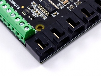
Phidgets Analog Inputs are designed to connect to simple sensors that report their data in the form of a 0-5V analog signal. There are two types of sensors that fall under this category: Ratiometric and Non-Ratiometric. Each Analog Input channel can be opened with either the VoltageRatioInput object or the VoltageInput object, thus supporting these two different types of sensors. |
Phidgets VINT Hub Port
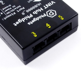
Phidgets VINT Hub Ports are primarily designed to connect to Phidgets VINT devices, which can be sensors, controllers, adapters, or data acquisition units. VINT devices use a digital protocol to communicate their data back to the VINT Hub via the VINT Hub Port. Each VINT Hub Port can also be opened with the following objects:
|
You can determine whether a Phidget has VINT ports or Analog Inputs by reading the product description on that Phidget's page on our website.
Software Objects
VoltageRatioInput
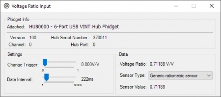
Ratiometric sensors output a signal that is proportional to the amount of voltage used to power them. For example, a 0-100°C ratiometric temperature sensor that is powered by a 4.5V supply will output a voltage signal proportional to that 4.5V. So if it's measuring 50°C, which is half of it's full measurement range, it would output 2.25V (half of 4.5V). If the power supply to this sensor changes even slightly, that 2.25V signal will also change slightly. Thus, in order to read a ratiometric sensor properly, you must constantly compare the voltage signal reported by the sensor to the voltage of the power supply that's powering the sensor.
In the case of a Phidgets Analog Input or VINT Hub Port, opening the device in VoltageRatioInput mode will automatically handle this, and provide you with a voltage ratio which ranges from 0 to 1 V/V (volts per volt). '0' denotes that the sensor is sending back a signal that is 0% of the voltage it's being provided, and '1' denotes that the sensor is sending back a signal that is 100% of the voltage it's being provided. In the temperature sensor example described earlier, the VoltageRatioInput object will report a ratio of 0.5 V/V, since 2.25V is half of 4.5V. You can use this ratio in combination with a formula from the sensor's datasheet or User Guide in order to convert it into the proper units.
For any sensors sold at Phidgets, you can set the SensorType property to have this conversion done automatically, since the libraries are loaded with all of the equations. Have a look at the SensorType enumeration in the Phidget22 API for a complete list of sensors that this can be done with.
VoltageInput
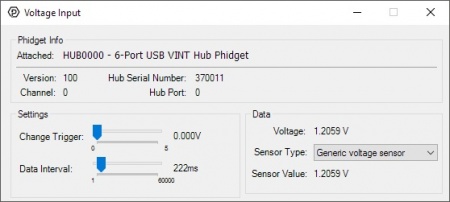
Non-Ratiometric sensors, on the other hand, don't care about how much voltage is being supplied to them, as long as it's within the specified range required to power them. This is because the sensor has a built-in regulator to ensure that it's getting a more-or-less steady supply.
To interface a non-ratiometric sensor, you can open your Phidgets Analog Input or VINT Hub port in VoltageInput mode, and you'll simply get data from the sensor in the form of a 0-5 volt value. Again, you can convert this voltage into a useful value using the equation found in the sensor's datasheet or User Guide.
For any sensors sold at Phidgets, you can set the SensorType property to have this conversion done automatically, since the libraries are loaded with all of the equations. Have a look at the SensorType enumeration in the Phidget22 API for a complete list of sensors that this can be done with.
DigitalInput
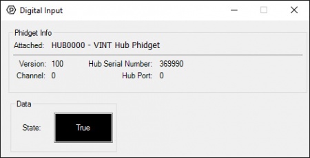
The DigitalInput software object is used to interface with switches or sensors with a boolean (yes-or-no) output. When you open a VINT port in DigitalInput mode, the white wire on the Phidget cable is used as the digital input, while the red and black wires remain as +5V power and ground, respectively.
DigitalOutput
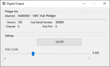
The DigitalOutput software object is used with LEDs and other small, low-power electronics. A VINT port in DigitalOutput mode can provide 3.3V when active and 0V when inactive. The white wire on the Phidget cable is the digital output, and the red and black wires remain as +5V power and ground, respectively.